Mechanical assembling hand with contraction function

A shrinking function and shrinking mechanism technology, applied in the field of manipulators, can solve problems such as the limitation of the working range of the mechanical assembly hand, the limitation of the working ability of the mechanical assembly hand, and the reduction of the practicability of the mechanical assembly hand, so as to prevent separation, reduce friction, and improve work efficiency. Effect

Inactive Publication Date: 2021-08-27
YANTAI ENG & TECH COLLEGE YANTAI TECHNICIAN INST
View PDF0 Cites 0 Cited by
  • Summary
  • Abstract
  • Description
  • Claims
  • Application Information

AI Technical Summary

Problems solved by technology

[0005] Aiming at the deficiencies of the prior art, the present invention provides a mechanical assembly hand with a contraction function, which has a wide application range and high safety, and solves the limitation of the working range of the mechanical assembly hand on the market. The mechanical assembl

Method used


Image

  • Mechanical assembling hand with contraction function
  • Mechanical assembling hand with contraction function
  • Mechanical assembling hand with contraction function

Examples


Embodiment 1

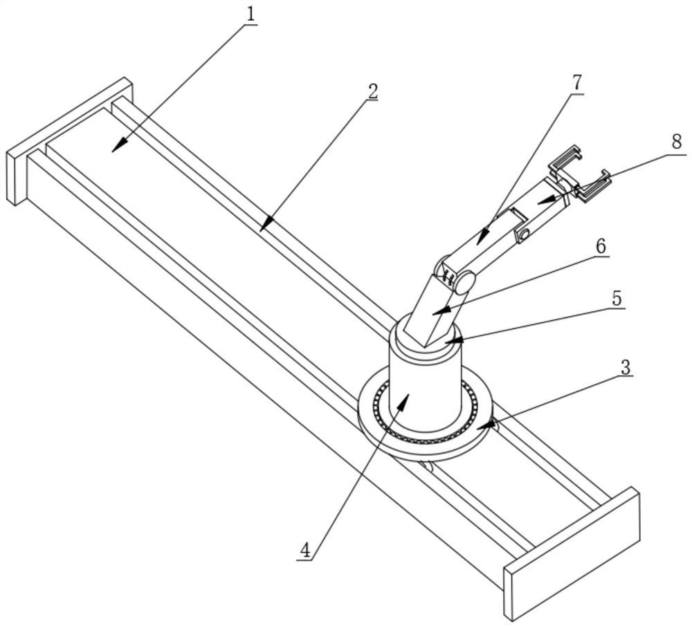
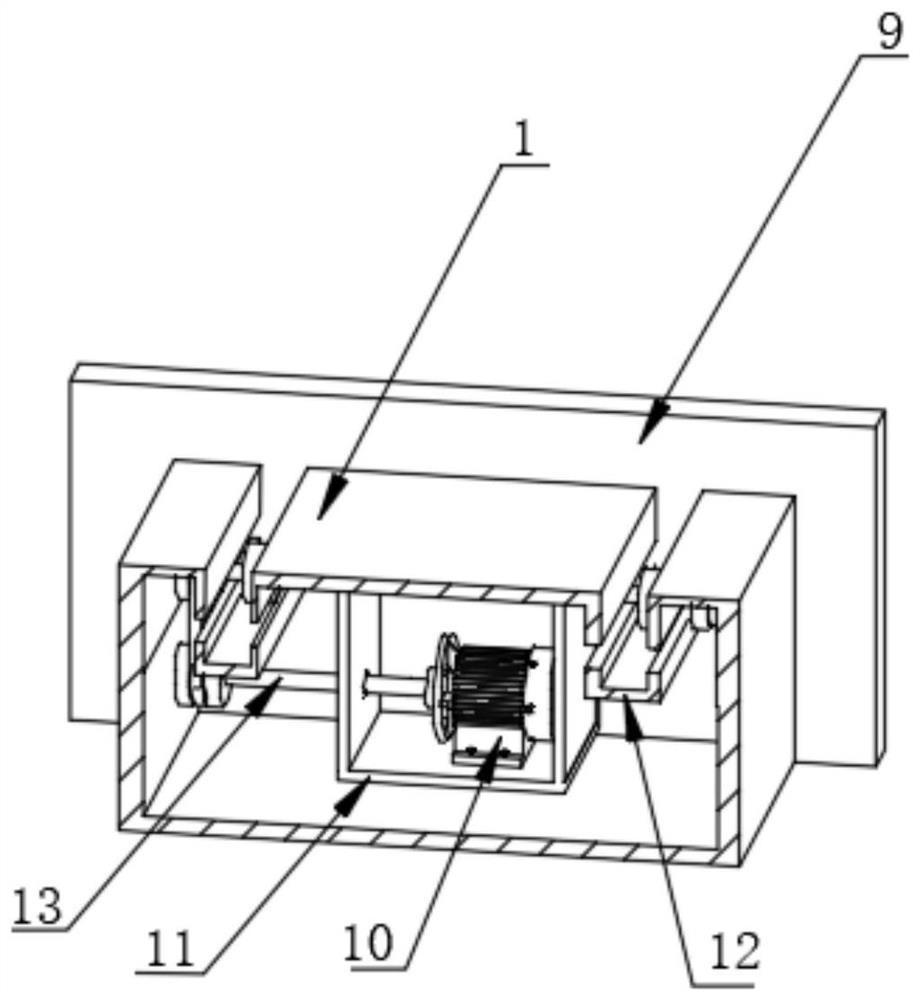
[0030]A mechanical assembly hand with contraction function, comprising a workbench 1, the upper surface of the workbench 1 is provided with a movable groove 2, the interior of the workbench 1 is fixedly installed with a sliding mechanism, and the upper surface of the movable groove 2 is provided with a moving block 3, The upper surface of the moving block 3 is provided with a rotating column 4, the upper surface of the rotating column 4 is fixedly connected with a connecting block 5, the upper surface of the connecting block 5 is fixedly connected with a large mechanical arm 6, and the upper end of the large mechanical arm 6 is movably connected with a small mechanical arm. One side of the outer surface of the arm 7 and the small mechanical arm 7 is provided with a telescopic column 8, and a retractable mechanism is installed inside the telescopic column 8. The sliding mechanism includes a protective shell 11, and a first motor 10 is fixedly installed inside the protective shell...

Embodiment 2

[0032] Embodiment 2: the difference based on Embodiment 1 is;

[0033] The upper surface of the moving block 3 is fixedly connected with a clamping block 19, and the inside of the moving block 3 is fixedly equipped with a center ball 24, and the lower surface of the rotating column 4 is fixedly connected with a rotating block 20, and the middle part of the rotating block 20 is provided with a clamping hole. The outer surface of the block 20 is provided with a clamping ring, one side of the outer surface of the center ball 24 is movably socketed in the clamping ring, the clamping block 19 is movably clamped with the clamping hole, and the inside of the rotating column 4 is fixedly equipped with a fixed block 21 , the inside of the fixed block 21 is fixedly installed with a second motor 25, the upper end of the second motor 25 is fixedly connected with a rotating gear 26, and the lower surface of the connecting block 5 is fixedly connected with a snap ring 27, and the middle part...

Embodiment 3

[0035] Embodiment 3: the difference based on embodiment 1 is;

[0036] The retraction mechanism includes a hydraulic press 30, one side of the outer surface of the hydraulic press 30 is fixedly connected with a closing plate 29, one side of the outer surface of the closing plate 29 is provided with an air inlet, and the other side of the outer surface of the hydraulic press 30 is fixedly connected with a movable column 33, The inside of the movable column 33 is movably connected with a telescopic rod 37, the outer surface of the telescopic rod 37 is provided with a return spring 31, the other end of the return spring 31 is fixedly connected with a sliding block 34, and the other side of the outer surface of the sliding block 34 is provided with a fixed plate 32, the other side of the outer surface of the fixed plate 32 is provided with a connecting plate 35, the two ends of the connecting plate 35 are fixedly connected with claws 36, the inside of the fixed plate 32 is provided...


PUM


Abstract

The invention relates to the technical field of manipulators, and discloses a mechanical assembling hand with a contraction function, which comprises a worktable; a movable groove is formed in the upper surface of the worktable; a sliding mechanism is fixedly mounted in the worktable; a movable block is arranged on the upper surface of the movable groove; a rotating column is arranged on the upper surface of the movable block; a connecting block is fixedly connected to the upper surface of the rotating column; a large mechanical arm is fixedly connected to the upper surface of the connecting block; a small mechanical arm is movably connected to the upper end of the large mechanical arm; a telescopic column is arranged on one side of the outer surface of the small mechanical arm; and a contraction mechanism is movably installed in the telescopic column. The invention solves the following problems: the working range of a mechanical assembling hand in the market is limited; the mechanical assembling hand can only work in the moving range of the mechanical assembling hand; a worker still needs to carry the mechanical assembling hand during long-distance carrying; the mechanical assembling hand cannot move, so that the working capacity of the mechanical assembling hand is limited; and the practicability of the mechanical assembling hand is greatly reduced.

Description

technical field [0001] The invention relates to the technical field of manipulators, in particular to a mechanical assembly hand with a contraction function. Background technique [0002] The manipulator is a kind of mechanical assembly hand with contraction function of modern robots. It is a machine equipment that realizes multi-station automatic handling of items. It replaces manual handling, saves labor costs, improves work efficiency, and prevents industrial accidents. Features of the manipulator: can be designed Pneumatic or mechanical fixtures and vacuum grippers are used in conjunction with it, and each manipulator is individually designed according to the actual application. Finally, the metal body of the manipulator is suitable for use in various industrial occasions. The translation and lifting of the transfer head are controlled by PLC or industrial computer And the action of the fixture, the completion of the set task, repeated, efficient and safe, the fixture is...

Claims


Application Information

Patent Timeline
IPC IPC(8): B65G47/90
CPCB65G47/902
Inventor 隋向东王文静王春荣邢向阳
Owner YANTAI ENG & TECH COLLEGE YANTAI TECHNICIAN INST
Why Eureka
Try Eureka