Double ducted ejector for aeroengine

An aero-engine and ducting technology, which is applied in the direction of rocket engine devices, machines/engines, jet propulsion devices, etc., can solve the problems of unchangeable working conditions, inability to separate internal and external exhaust, etc., so as to improve kinetic energy and ejection efficiency and gas mixing uniformity, and improve the effect of ejection efficiency

Active Publication Date: 2022-07-29
NORTHWESTERN POLYTECHNICAL UNIV +1
View PDF8 Cites 0 Cited by
  • Summary
  • Abstract
  • Description
  • Claims
  • Application Information

AI Technical Summary

Problems solved by technology

[0004] In order to overcome the shortcomings in the prior art that the aviation ejector cannot change the working conditions and cannot exhaust the inner and outer parts separately, the present invention proposes a double-duct ejector for aero-engines

Method used


Image

  • Double ducted ejector for aeroengine
  • Double ducted ejector for aeroengine
  • Double ducted ejector for aeroengine

Examples


Embodiment Construction

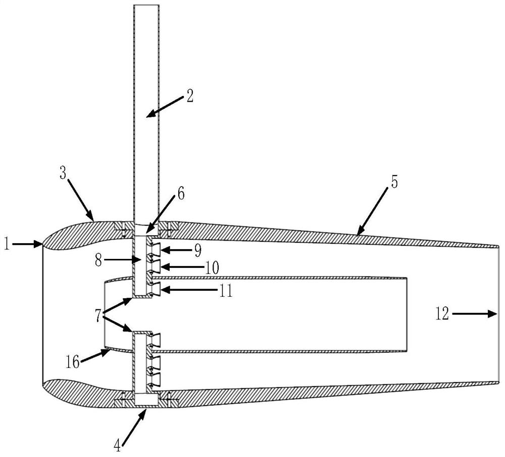
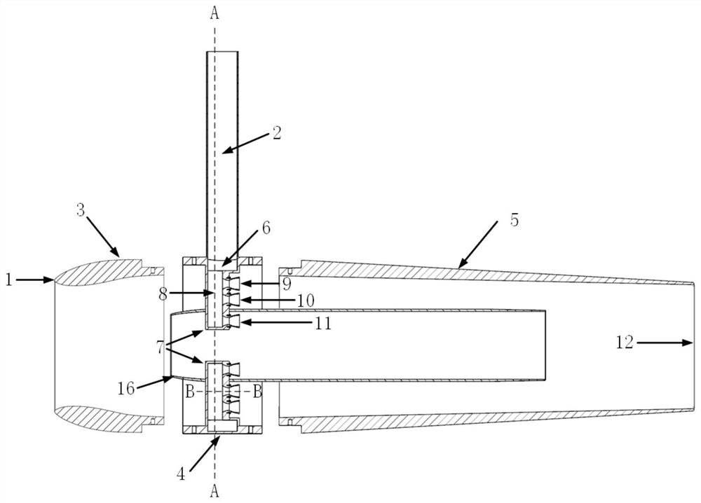
[0037] This embodiment is a dual-duct ejection device for aero-engines, including a high-pressure air intake duct 2, an ejector, an inner duct body 16, a leading edge stabilizer 7 and a variable Mach number nozzle. The ejector is used as the outer channel body, and the inner channel body is located in the ejector.

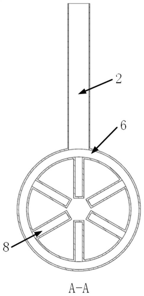
[0038] The ejector is divided into an ejector front section 3 , an ejector middle section 4 and an ejector rear section 5 . There are six said steady flow branch plates 7, and the airflow inlet end of each steady flow branch plate is welded to the inner surface of the shell of the middle section 4 of the ejector, and is connected to the annular high-pressure gas source on the middle section of the ejector. The chamber 6 is communicated; the closed end of each flow-stabilizing branch plate 7 passes through the flow-stabilizing branch plate insertion hole on the shell of the inner channel body 16 and extends into the inner channel body. The inner channel body is wel...


PUM


Abstract

The utility model relates to a double bypass ejector device for aero-engine, and the inner channel body is located in the ejector. The airflow inlet ends of each flow-stabilizing branch plate are respectively fixed on the inner surface of the shell of the middle section of the ejector, and communicate with the annular high-pressure gas source chamber on the middle section of the ejector; the closed end of each flow-stabilizing branch plate is located in the inner channel in vivo. The outer duct of the ejection device is formed between the inner surface of the ejector and the outer surface of the inner duct body, and the inner duct body of the ejection device is formed by the inner hole of the inner duct body. The invention changes the exhaust speed of the internal and external injection through the distributed variable Mach number nozzle, realizes the variable bypass ratio injection, and can carry out the power simulation of the turbofan engine, and the intake and exhaust positions of the internal channel of the ejector are located In the outer duct, the high-speed mixed ejection gas of the inner duct body can further eject the outer duct mixed gas at the outlet of the duct support plate, which realizes the secondary ejection of the duct, further improves the kinetic energy of the outer duct mixed ejection flow, and also improves the overall ejection efficiency.

Description

technical field [0001] The invention relates to the technical field of aero-engine testing, in particular to a variable-working-condition multi-nozzle distributed double-duct ejector device for aero-engines. Background technique [0002] With the extensive application of new concepts, new layouts, and new technologies in the whole aero-engine test, such as combined power supersonic free intake, vector thrust engine exhaust, and large bypass ratio engines, the test envelope has been continuously expanded. Costs continue to rise, and the technical risks of trials become greater. Therefore, it is necessary to develop low-cost, low-risk and high-efficiency model test simulation technology. The simulation of the engine power plant, the ejector is the core component. Two streams of different pressures are mixed with each other in the ejector and energy exchange occurs to form a fluid of mixed pressure. [0003] The ejector can obtain the intake and exhaust effect of the engine ...

Claims


Application Information

Patent Timeline
Patent Type & Authority Patents(China)
IPC IPC(8): F02K9/96
CPCF02K9/96
Inventor 杜旭博杨青真陈鹏飞杨皓琦
Owner NORTHWESTERN POLYTECHNICAL UNIV
Why Eureka
Try Eureka