Al technical title is built by PatSnap Al team. It summarizes the technical point description of the patent document.
A technology of detection device and magnetic sheet, applied in the direction of fluid pressure actuation device, etc., can solve the problems of high system cost, poor applicability, complicated structure of pneumatic system, etc., and achieve the effect of accurate position detection, less restrictive conditions and strong applicability
Active Publication Date: 2021-08-27
CHONGQING IND POLYTECHNIC COLLEGE
View PDF11 Cites 0 Cited by
Summary
Abstract
Description
Claims
Application Information
AI Technical Summary
This helps you quickly interpret patents by identifying the three key elements:
Problems solved by technology
Method used
Benefits of technology
Problems solved by technology
[0003] However, the former pneumatic system has a simple structure, accurate detection, and low cost of the pneumatic system, while the latter has a complex structure and high system cost, and sometimes the installation position of the pneumatic travel valve or electrical proximity switch is limited, which brings inconvenience to the cylinder position detection
Therefore, the cylinder position detection device utilizing the magnetic switch is the most widely used, and has met most of people's needs, but there are still some deficiencies, mainly the following problems: First, the electrical signal must be used to cooperate with the electrical control system to complete the cylinder position. There are certain restrictions on detection. Second, it is inconvenient to use electrical control in places with explosion-proof requirements. The applicability is poor, and it is difficult to meet the needs of special scenarios. Significantly increases the cost of the entire pneumatic system
Method used
Image
Click on the blue label to locate the original text in one second.
Reading with bidirectional positioning of images and text.
Examples
Embodiment Construction
[0017] The following will clearly and completely describe the technical solutions in the embodiments of the present invention with reference to the accompanying drawings in the embodiments of the present invention. Obviously, the described embodiments are only some, not all, embodiments of the present invention. Based on the embodiments of the present invention, all other embodiments obtained by persons of ordinary skill in the art without making creative efforts belong to the protection scope of the present invention.
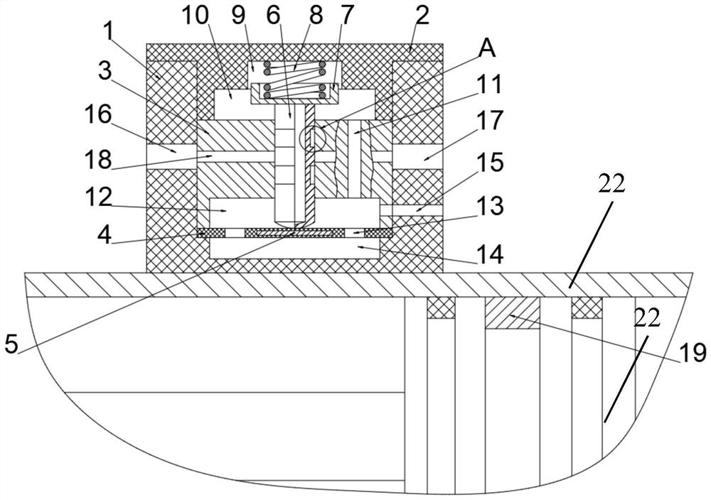
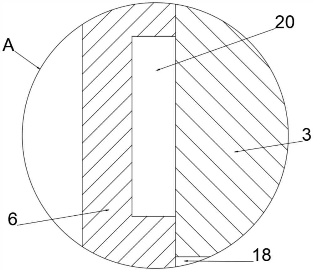
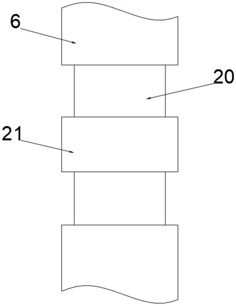
[0018] see Figure 1-2 , the present invention provides a technical solution: a magnetic-gas position detection device, including a main body 1, an upper cover 2, a valve body 3, a diaphragm 4, a magnetic sheet 5, a valve core 6, a spring seat 7, a telescopic spring 8, First chamber 9, second chamber 10, first conduction hole 11, third chamber 12, second conduction hole 13, fourth chamber 14, exhaust port 15, air supply port 16, signal port 17. Valve hole 18,...
PUM
Abstract
The invention discloses a magnetic-gas position detection device. The magnetic-gas position detection device comprises a main body, an upper cover, a valve body, a diaphragm, a magnetic sheet, a valve element, a spring seat, a telescopic spring, a first containing cavity, a second containing cavity, a first through hole, a third containing cavity, second through holes, a fourth containing cavity, an exhaust opening, a gas supply opening, a signal opening, a valve hole, a magnetic ring and an annular groove, wherein the bottom of the main body is fixedly connected with the outer wall of an air cylinder, the outer edge of the top of the main body is fixedly connected with the outer edge of the bottom of the upper cover, the inner edge of the bottom of the upper cover makes contact with the outer edge of the top of the valve body, and the outer edge of the bottom of the valve body makes contact with the outer edge of the top of the diaphragm. According to the magnetic-gas position detection device, by detecting strong magnetic signals of the magnetic ring arranged on a piston, converting the strong magnetic signals into air pressure signals and outputting the air pressure signals, the motion position of the air cylinder is detected, no electric power is needed, limiting conditions are few, the applicability is high, the magnetic-gas position detection device can be applied to special occasions with anti-explosion requirements and the like, the structure is simple, detection is accurate, and the cost of a pneumatic system is low.
Description
technical field [0001] The invention relates to the technical field of position detection devices, in particular to a magnetic-gas position detection device. Background technique [0002] A cylinder is an actuator that converts compressed air energy into mechanical energy output in a pneumatic transmission system. It is generally composed of a cylinder barrel, an end cover, a piston, a piston rod, and a seal. It is usually necessary to detect the position of the piston rod during use. At present, there are mainly two types of traditional position detection methods: one is to install a magnetic switch on the cylinder barrel and a magnetic ring on the piston. When the cylinder moves, the piston drives the strong magnetic magnetic ring to move together. When the magnetic ring moves to When the magnetic switch is in position, the magnetic force of the magnetic ring acts on the reed switch of the magnetic switch, and the contacts of the reed switch are turned on or off, and then ...
Claims
Application Information
Patent Timeline
Application Date:The date an application was filed.
Publication Date:The date a patent or application was officially published.
First Publication Date:The earliest publication date of a patent with the same application number.
Issue Date:Publication date of the patent grant document.
PCT Entry Date:The Entry date of PCT National Phase.
Estimated Expiry Date:The statutory expiry date of a patent right according to the Patent Law, and it is the longest term of protection that the patent right can achieve without the termination of the patent right due to other reasons(Term extension factor has been taken into account ).
Invalid Date:Actual expiry date is based on effective date or publication date of legal transaction data of invalid patent.