Battery fault or failure detection equipment and use method thereof

A technology for detecting equipment and battery faults, applied in the direction of measuring electricity, measuring devices, measuring electrical variables, etc., can solve the problems of inability to carry out continuous detection, poor continuity of the detection process, and reduce detection efficiency, so as to improve high-efficiency classification, electric power, etc. Easy to adjust and improve the effect of continuity

Active Publication Date: 2021-08-27
JINZHONG POWER SUPPLY COMPANY OF STATE GRID SHANXI ELECTRIC POWER
View PDF14 Cites 5 Cited by
  • Summary
  • Abstract
  • Description
  • Claims
  • Application Information

AI Technical Summary

Problems solved by technology

[0003] However, in actual use, such as general testing equipment, it needs to be tested one by one during use, and can only be operated after the first battery is tested The second battery is placed for detection, the continuity of the detection process is poor, and the continuous detection operation cannot be performed, which greatly reduces the detection efficiency. At the same time, after the detection, the failed battery is mixed with the faulty battery and the normal battery, which is not easy to classify and is easy to confuse. Waste detection time, more time-consuming and labor-intensive, poor practicability

Method used


Image

  • Battery fault or failure detection equipment and use method thereof
  • Battery fault or failure detection equipment and use method thereof
  • Battery fault or failure detection equipment and use method thereof

Examples


Embodiment Construction

[0032] The following will clearly and completely describe the technical solutions in the embodiments of the present invention with reference to the accompanying drawings in the embodiments of the present invention. Obviously, the described embodiments are only some, not all, embodiments of the present invention. Based on the embodiments of the present invention, all other embodiments obtained by persons of ordinary skill in the art without making creative efforts belong to the protection scope of the present invention.

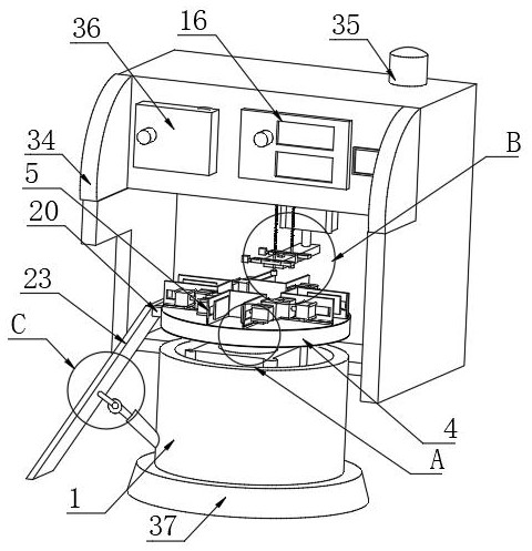
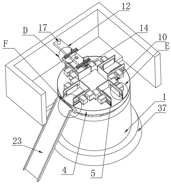
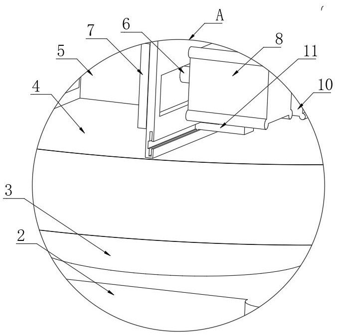
[0033] as attached Figure 1-8The shown one is used for battery failure or failure detection equipment, including a rotary table 1, a continuous detection mechanism is embedded in the top of the rotary table 1, and a classification mechanism is installed on one side of the continuous detection mechanism;

[0034] The continuous detection mechanism includes a transmission motor 2 arranged at the embedded position at the top of the rotary table 1, the output end...


PUM


Abstract

The invention discloses battery fault or failure detection equipment and a use method thereof, and particularly relates to the technical field of battery detection, the battery fault or failure detection equipment comprises a rotating table, a continuous detection mechanism is embedded in the top end of the rotating table, and a classification mechanism is mounted on one side of the continuous detection mechanism; the continuous detection mechanism comprises a transmission motor arranged at the embedding position of the top end of the rotating table. By arranging the continuous detection mechanism and the classification mechanism, a plurality of batteries can be continuously placed, one battery is detected to the next time after detection, the placement time is shortened, continuous disc detection is carried out, the detection continuity is effectively improved, the detection is more efficient, time and labor are saved, classified conveying is carried out, the efficient classification performance is effectively improved, the use is more convenient, confusion can be avoided, and moreover, a guide inclined plate can realize stable rotation in the rotating process, so that the stability of stable sliding of the batteries is better, and the practicability is better.

Description

technical field [0001] The present invention relates to the technical field of battery detection, and more specifically, the present invention relates to a battery fault or failure detection device and a usage method thereof. Background technique [0002] A battery refers to a cup, tank or other container or part of a composite container that contains an electrolyte solution and a metal electrode to generate an electric current, and is a device that converts chemical energy into electrical energy. It has positive pole and negative pole. As technology advances, batteries generally refer to small devices that can generate electricity. Such as solar cells. The performance parameters of the battery mainly include electromotive force, capacity, specific energy and resistance. During the use of the battery, it is necessary to perform testing operations to know whether the battery quality is qualified, which requires the use of testing equipment for testing operations. [0003] ...

Claims


Application Information

Patent Timeline
Patent Type & Authority Applications(China)
IPC IPC(8): G01R31/01G01R31/385B07C5/36B65G29/00B65G47/74B65G47/82
CPCG01R31/01G01R31/385B07C5/362B65G29/00B65G47/74B65G47/82Y02E60/10
Inventor 王晓辉杨爱晟冯霆郑素珍李永伟郭晓峻高飞
Owner JINZHONG POWER SUPPLY COMPANY OF STATE GRID SHANXI ELECTRIC POWER
Why Eureka
Try Eureka