Strain clamp shell and strain clamp comprising same
What is AI technical title?
AI technical title is built by PatSnap AI team. It summarizes the technical point description of the patent document.
A tension clamp, housing technology, used in cable installation, cable suspension, overhead line/cable equipment, etc.
Active Publication Date: 2021-08-27
FOGANG XINYUAN HENGYE CABLE TECH CO LTD
View PDF5 Cites 1 Cited by
Summary
Abstract
Description
Claims
Application Information
AI Technical Summary
This helps you quickly interpret patents by identifying the three key elements:
Problems solved by technology
Method used
Benefits of technology
Problems solved by technology
The tension clamps connect the shell body (clamp shell) to the electric tower through a pull rod or a hanging plate, which requires considerable strength. Most of the main tubes of the existing clamp shells are single-layer main tubes, which are not very good. Satisfies the harsh conditions of use of tension clamps
Method used
Image
Click on the blue label to locate the original text in one second.
Reading with bidirectional positioning of images and text.
Examples
Embodiment 1
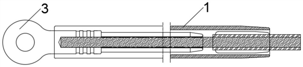
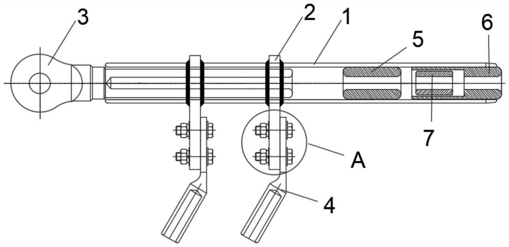
[0058] see Figure 1-5 , an embodiment provided by the present invention: a tension clamp housing, comprising a main body tube 1 and a steel anchor 3, the main body tube 1 is a hollow structure, and one end of the main body tube 1 is fixedly connected with the steel anchor 3. The other end of the main body tube 1 is provided with a first lined aluminum tube 5 and a second lined aluminum tube 6. The first lined aluminum tube 5 and the second lined aluminum tube 6 are both hollow structures. The first aluminum lined pipe 5 is located on the side of the main pipe 1 near the steel anchor 3 of the second aluminum lined pipe 6 , and a reinforcing steel pipe 7 is arranged in the second aluminum lined pipe 6 .
[0059] Preferably, grooves 14 and partitions 15 are provided on the outer wall of the main body pipe 1. The grooves 14 and partitions 15 are distributed at intervals, and a number of the grooves 14 and partitions 15 are provided according to different application occasions. 1...
Embodiment 2
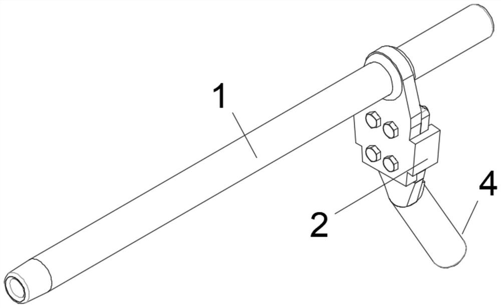
[0064] see Figure 6-9 , On the basis of the above-mentioned Embodiment 1, a tensile wire clip includes a tensile wire clip shell described in Embodiment 1, and the tensile wire clip also includes a drainage plate 2 and a drainage wire clip 4, The drainage plate 2 is fixed on the main body pipe 1 , the drainage plate 2 and the drainage wire clip 4 are provided with bolt holes 8 , and the drainage wire clip 4 and the drainage plate 2 are tightened by bolts 9 . 12, the fastening bolts 9 and 12 are sleeved with flat washers 10 on both sides of the drainage plate 2 and the drainage clip 4, and the fastening bolts outside the flat washer 10 on one side of the nut 12 are close to each other. 9 is also sleeved with a spring washer 11 .
[0065] Preferably, the drainage plate 2 includes a first wedge-shaped plate 201, a C-shaped groove wall 202, and a socket hole 203. The first wedge-shaped plate 201 is provided with a socket hole 203 on the upper side, and the socket hole 203 is use...
Embodiment 3
[0069] see Figure 10-12 On the basis of the above-mentioned Embodiment 2, a quick plug-in device 16 can also be arranged in the drainage connection hole 403, and the quick plug-in device 16 includes:
[0070] Push block 1601, first linkage member 1602, pressure bin 1603, movable bin 1604, first spring 1605, first hinge rod 1606, second linkage member 1607, second hinge rod 1608, balance member 1609, second spring 1610, The clamping chamber 1611, the first clamping block 1612, the second clamping block 1613, the synchronizing gear 1614, the connecting plate 1615, the clamping shaft 1616, the pressure piece 1617;
[0071] The outer wall of the pressure chamber 1603 is fixed with the drainage connection hole 403 , the pressure chamber 1603 is a semi-closed structure, the inside of the pressure chamber 1603 is connected with one end of the first spring 1605 , and the inner side of the pressure chamber 1603 is a movable chamber 1604, the first linkage member 1602, the second link...
PUM
Abstract
The invention discloses a strain clamp shell and a strain clamp comprising same. The strain clamp shell comprises a main body pipe and a steel anchor, the main body pipe is of a hollow structure, one end of the main body pipe is fixedly connected with the steel anchor, and a first lining aluminum pipe, a second lining aluminum pipe and a reinforcing steel pipe are arranged in the other end of the main body pipe; the strain clamp comprises the strain clamp shell, a drainage plate and a drainage wire clamp, the drainage plate is fixed on the main body pipe, the drainage wire clamp is connected with the drainage plate through a bolt, a wedge-shaped groove is formed in the drainage plate, and the wedge-shaped plate on the drainage wire clamp is sleeved in the wedge-shaped groove. The first lining aluminum pipe, the second lining aluminum pipe and the reinforcing steel pipe are arranged in the main body pipe of the hollow structure, the strength of the main body pipe is guaranteed, the main body pipe can better adapt to harsh using conditions, the drainage plate is provided with the wedge-shaped groove and is used in cooperation with the wedge-shaped drainage wire clamp, and when the drainage wire clamp moves downwards, the wedge-shaped structure enables the drainage plate and the drainage wire clamp to be matched tighter and tighter, and even if the fixing bolt is loosened, the C-shaped groove enables the drainage plate not to be separated easily.
Description
technical field [0001] The invention relates to the field of wire clips, in particular to a tensile wire clip casing and a tensile wire clip containing the same. Background technique [0002] With the rapid development of power application facilities in distribution networks, in high-voltage and ultra-high-voltage overhead power systems, in order to anchor and tension both ends of carbon fiber composite core wires to poles or towers, tension clamps are required. The tension clamps connect the shell body (clamp shell) to the electrical tower through tie rods or hanging plates, which requires considerable strength. It can meet the strict conditions of use of tension clamps. SUMMARY OF THE INVENTION [0003] The purpose of the present invention is to provide a tension clamp housing and a tension clamp containing the same, so as to solve the problems raised in the above-mentioned background art. [0004] In order to achieve the above purpose, the present invention provides t...
Claims
Application Information
Patent Timeline
Application Date:The date an application was filed.
Publication Date:The date a patent or application was officially published.
First Publication Date:The earliest publication date of a patent with the same application number.
Issue Date:Publication date of the patent grant document.
PCT Entry Date:The Entry date of PCT National Phase.
Estimated Expiry Date:The statutory expiry date of a patent right according to the Patent Law, and it is the longest term of protection that the patent right can achieve without the termination of the patent right due to other reasons(Term extension factor has been taken into account ).
Invalid Date:Actual expiry date is based on effective date or publication date of legal transaction data of invalid patent.

