Externally-hung cable protection device and control system thereof

A protection device and control system technology, which is applied in the direction of cable suspension device, adjustment/maintenance of mechanical tension, etc. It can solve the problems of high tension force, easy injury of people when the cable is thrown, and the inability to adjust the length, etc., to achieve the degree of automation High, avoiding the effect of cable swinging and hurting personnel

Inactive Publication Date: 2021-08-27
河南胜凡信息科技有限公司
View PDF0 Cites 3 Cited by
  • Summary
  • Abstract
  • Description
  • Claims
  • Application Information

AI Technical Summary

Problems solved by technology

[0006] In view of the above situation, in order to overcome the defects of the prior art, the present invention provides an external cable protection device and its control system, which effectively solves the problem that the cable of the existing device swings under the influence of extreme weather and causes excessive tension. Breaking, and the cable is easy to hurt people when the line is thrown, and the length cannot be adjusted independently according to the season

Method used


Image

  • Externally-hung cable protection device and control system thereof
  • Externally-hung cable protection device and control system thereof
  • Externally-hung cable protection device and control system thereof

Examples


Embodiment 1

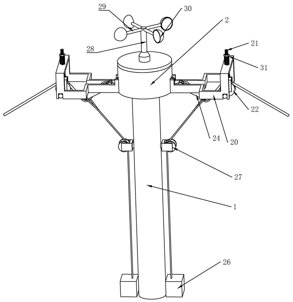
[0036] Embodiment 1, the present invention is an external cable protection device and its control system, including a utility pole 1, characterized in that the upper end surface of the utility pole 1 is fixedly connected with a tensioning chamber 2, and the wires and cables can pass through the tensioning chamber 2. The bin 2 is also supported by the tension bin 2, the tension bin 2 is provided with a winding module, the winding module can be a winding machine, which can wind the wires and cables passing through the tension bin 2 Tightening function, the upper end surface of the tensioning chamber 2 is provided with a wind drive module, the wind drive module can be a rotating fan, when the wind blows outside, it can drive the fan to rotate, the lower end surface of the wind drive module is fixedly connected There is a rotating disk 3, which can rotate together with the wind drive module. The centrifugal block 4 is slidably connected to the rotating disk 3. When the rotating dis...

Embodiment 2

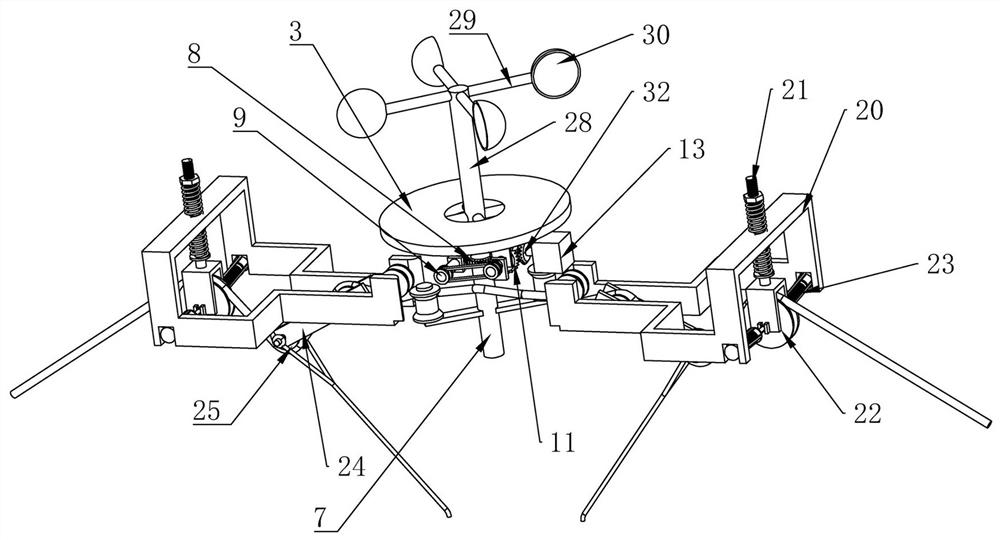
[0041] Embodiment 2. On the basis of Embodiment 1, the winding module includes a winding rod 7 that is rotatably connected in the Zhangjin bin. Winding wheels are provided on both sides of the winding rod 7. When the cable goes around the coil When winding the rod 7, the winding rod 7 rotates, which will drive the two winding wheels to tighten the cable. It should be noted that in order to make the winding wheels tighten the cable, the cable needs to be located Between the two winding wheels, one end of the winding rod 7 is coaxially fixedly connected with a worm 8, and one side of the worm 8 is meshed with a worm 9 which is rotatably connected to the tensioning chamber 2, and by setting the worm 9 of the worm 8 , the device can be self-locked to prevent the cable from loosening. The other side of the turbine 8 is provided with a tensioning bevel gear 10 and a loosening bevel gear 11 that are slidably connected to the tensioning chamber 2. The tensioning cone One side of the g...

Embodiment 3

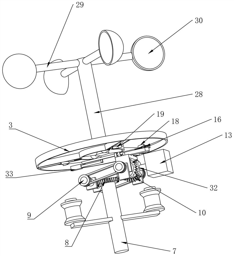
[0046] Embodiment 3, on the basis of Embodiment 2, the drive plate 12 is provided with a drive rod 14 rotatably connected to the tensioning chamber 2 on one side, and a chute 15 is opened on the drive plate 12. The other end of the driving rod 14 is slidably connected in the chute 15, when the driving rod 14 rotates on the tensioning chamber 2, it can drive the driving plate 12 to slide on the tensioning chamber 2;

[0047] The drive rod 14 is fixedly connected with a reversing gear 16, and one side of the reversing gear 16 is meshed with a reversing rack 17 that is slidably connected to the tensioning chamber 2, and the reversing rack 17 is a The side is fixedly connected with a passive arc plate 18, and one side of the centrifugal block 4 is fixedly connected with an active arc plate 19. When the centrifugal block 4 moves on the rotating disk 3 under the action of centrifugal force, the active arc plate on the centrifugal block 4 19 will be in contact with the passive arc pl...


PUM


Abstract

The invention relates to an externally-hung cable protection device and a control system thereof, and effectively solves the problems that a cable of an existing device is broken due to too large tensioning force caused by swinging of the cable, people are easily hurt when the cable is thrown, and the length cannot be autonomously adjusted along with seasons. According to the technical scheme, the protection device comprises a telegraph pole body, a tensioning bin is fixedly connected to the upper end of the telegraph pole body, a winding module is arranged in the tensioning bin, a wind power driving module is arranged on the upper end face of the tensioning bin, a rotating disc is fixedly connected to the lower end face of the wind power driving module, a centrifugal block is slidably connected with the interior of the rotating disc, a reset contact sensor is arranged on one side of the centrifugal block, and a driving contact sensor is arranged on the other side of the centrifugal block. According to the invention, the wind power driving module and the pay-off machine are arranged, the device is adjusted through a wind bowl, the automation degree is high, take-up and pay-off adjustment can be autonomously conducted on a cable along with the change of the environment, the cable is effectively protected, accidents that people are hurt by the cable are prevented, and high practicability and applicability are achieved.

Description

technical field [0001] The invention relates to the technical field of power transmission cables, in particular to an external cable protection device and a control system thereof. Background technique [0002] The power transmission cables between utility poles are generally in an arc-shaped bending state; when the power transmission cables tend to be straight, the greater the tension they are subjected to; when the power transmission cables are too curved, the two The length of the power transmission cable between adjacent utility poles will also be too long, and the overlong power transmission cable will make the weight of the power transmission cable between two adjacent utility poles too large, and then there will be other problems. The higher the tension, the greater the tension; therefore, the actual power transmission cables between the utility poles are in a relatively moderate arc-shaped bending state. [0003] Due to the influence of thermal expansion and contrac...

Claims


Application Information

Patent Timeline
Patent Type & Authority Applications(China)
IPC IPC(8): H02G7/05H02G7/02B65H75/44B65H75/38
CPCB65H75/38B65H75/4484B65H2701/34H02G7/02H02G7/05
Inventor 李晓阳
Owner 河南胜凡信息科技有限公司
Why Eureka
Try Eureka