
Multi-output-shaft type independent voltage regulation variable frequency motor

A technology of multiple output shafts and variable frequency motors, applied in the direction of electromechanical devices, electrical components, shielding electromagnetic fields, etc., can solve the problems of low winding utilization, large end loss, large motor volume, etc., and achieve wide speed adjustment range and good speed Adjustability and wide application scenarios

Active Publication Date: 2021-08-27
ZHENGZHOU UNIV +1
View PDF9 Cites 0 Cited by
  • Summary
  • Abstract
  • Description
  • Claims
  • Application Information

AI Technical Summary

Problems solved by technology

In order to form a loop, the winding structure of the traditional motor needs to be provided with a loop winding. The loop winding usually needs to be arranged across the slot, which makes the motor appear too long end winding, and the ineffective length of the motor winding will increase, and even exceed the effective length. Too long end windings have many disadvantages, such as low winding utilization, serious end magnetic flux leakage, excessive end loss, etc., especially for dual-rotor different-speed motors, to achieve different speeds of two different rotors, usually requires additional mechanical devices or two sets of independent windings, so the winding utilization will be lower and the end problem will be more serious
In applications that require multiple (three or more) output shaft outputs, multiple motors are usually required to work together, which makes the above shortcomings more obvious, and the motor occupies a larger volume
And when the motor winding fails, due to the small air gap space, it is usually necessary to pull out the rotor to replace the winding. All windings need to be replaced, which greatly increases the difficulty of maintenance and the maintenance cycle is longer

Method used


Image

  • Multi-output-shaft type independent voltage regulation variable frequency motor
  • Multi-output-shaft type independent voltage regulation variable frequency motor
  • Multi-output-shaft type independent voltage regulation variable frequency motor

Examples


Embodiment 1

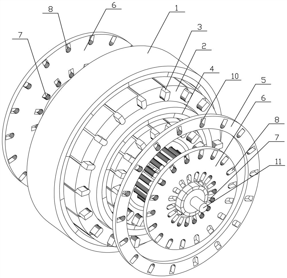
[0043] This embodiment provides a multi-output shaft variable-frequency variable-voltage speed-regulating motor, such as figure 1 As shown, it includes N stator-rotor units nested in sequence, each stator-rotor unit has an output shaft 11, and the output shafts 11 of any two adjacent stator-rotor units are arranged on different sides of the motor; preferably, In this embodiment, the stator and rotor units are sorted from the inside to the inside, the innermost stator and rotor unit is the first stator and rotor unit, and the outermost stator and rotor unit is the Nth stator and rotor unit;

[0044] A voltage regulation and frequency modulation device is connected in series between the armature windings of two adjacent stator and rotor units. The armature winding input terminal of the first stator and rotor unit is connected to the drive power supply, and the armature winding of the i-th stator and rotor unit is connected to the input line. terminal is connected to the outlet e...

Embodiment 2

[0057] The difference between this embodiment and embodiment 1 is: as figure 2 As shown, the voltage regulating circuit also includes a first gating unit, the first terminal of the first gating unit is connected to the armature winding outlet end of the i-1th stator and rotor unit, and the first gating unit The second terminal of the first gate unit is directly connected to the DC voltage regulator circuit through the AC to DC circuit, and the third terminal of the first gating unit is directly connected to the DC voltage regulator circuit; The conduction and disconnection between the i-1th stator-rotor unit’s armature winding output terminal to realize the alternating current into direct current and send it to the DC voltage regulating circuit, or the i-1st stator-rotor unit When the armature winding of the unit outputs direct current, the direct current is directly sent to the direct current voltage regulating circuit;

[0058] The frequency modulation circuit also include...

Embodiment 3

[0075] The difference between this embodiment and embodiment 1 or 2 is: as image 3 and Figure 4 As shown, the innermost stator-rotor unit is an inner-rotor outer-stator structure, and the remaining stator-rotor units are an outer-rotor inner-stator structure; a magnetic isolation ring 4 is embedded between the innermost stator-rotor unit and its adjacent stator-rotor unit .

[0076] The magnetic circuit of the stator and rotor 1 of the inner stator and rotor unit and the outer stator and rotor unit can be isolated by the magnetic isolation ring 4, so that the magnetic circuits of the stator and rotor 1 of the two layers of the stator and rotor unit of the motor do not interfere with each other, Furthermore, independent control of different operating frequencies of rotors 1 of different layers can be realized through the independent interlayer conductors provided at the ends to transfer the frequency conversion drive end rings, so as to realize the independent operation of d...


PUM


Abstract

The invention provides a multi-output-shaft type independent voltage regulation variable frequency motor which comprises N stator and rotor units which are sequentially arranged in a nested mode, wherein each stator and rotor unit is provided with an output shaft; one voltage and frequency regulating device is connected in series between the armature windings of every two adjacent stator and rotor units; the wire inlet end of the armature winding of the first stator and rotor unit is connected with a driving power supply, and the wire inlet end of the armature winding of the ith stator and rotor unit is connected with the wire outlet end of the armature winding of the (i-1) th stator and rotor unit through one voltage and frequency regulating device; the outlet end of the armature winding of the Nth stator and rotor unit is short-circuited through a short-circuit device, wherein i belongs to [2, N]; and the voltage and frequency regulating device is used for providing a corresponding driving power supply for the armature winding wire inlet end of the ith stator and rotor unit by utilizing the output voltage of the armature winding wire outlet end of the (i-1) th stator and rotor unit according to the frequency adjusting instruction and / or the voltage adjusting instruction so as to adjust the rotating speed of the output shaft of the ith stator and rotor unit and / or the voltage of the armature winding wire inlet end.

Description

technical field [0001] The invention relates to a variable-frequency and speed-regulating motor, in particular to a multi-output shaft independent voltage-regulating and variable-frequency motor. Background technique [0002] In the motor winding structure, only a section of winding placed in the slot can directly affect the output power of the motor, so it is called the effective length of the winding. In order to form a loop, the winding structure of the traditional motor needs to be provided with a loop winding. The loop winding usually needs to be arranged across the slot, which makes the motor appear too long end winding, and the ineffective length of the motor winding will increase, and even exceed the effective length. Too long end windings have many disadvantages, such as low winding utilization, serious end magnetic flux leakage, excessive end loss, etc., especially for dual-rotor different-speed motors, to achieve different speeds of two different rotors, usually r...

Claims


Application Information

Patent Timeline
Patent Type & Authority Applications(China)
IPC IPC(8): H02K1/16H02K13/00H02K16/00H02K11/01H02K11/30
CPCH02K1/16H02K13/003H02K16/00H02K11/01H02K11/30
Inventor 司纪凯魏彦企聂瑞陈延李森程志平李忠文王东署辛建斌张天翔
Owner ZHENGZHOU UNIV
Learn More