Phased-array antenna system with online internal monitoring function and internal monitoring method
A phased array antenna and function technology, applied in the field of radio frequency communication, can solve the problems of increasing volume and weight cost, and achieve the effect of improving maintainability and reducing miniaturization
- Summary
- Abstract
- Description
- Claims
- Application Information
AI Technical Summary
Problems solved by technology
Method used
Image
Examples
Embodiment 1
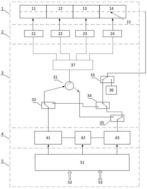
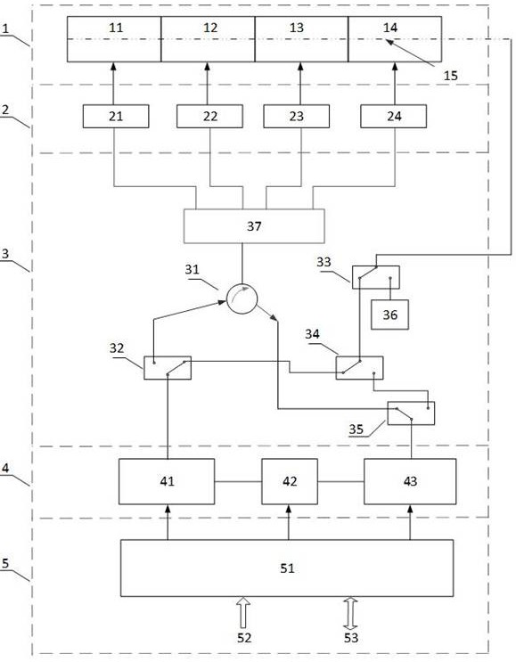
[0038] A phased array antenna system with in-line monitoring, see attached figure 1 , figure 2 , including an antenna array 1 , a TR component 2 , a radio frequency switch network 3 , a frequency conversion component 4 , a signal processor 5 and a coupling network 15 .
[0039] The antenna array 1 is a signal transmitting and receiving device, which is responsible for converting the "bound" electromagnetic field signal in the TR component and the "free" electromagnetic wave signal in space according to the agreed rules.
[0040] The coupling network 15, as an in-line monitoring network link, can be arranged anywhere in the phased array antenna system in principle, but for the comprehensiveness and systematicness of the online monitoring, the coupling network 15 is integrated with the antenna array 1 Design, that is, the monitoring network directly collects the coupling signal of each antenna unit in the antenna array 1, and the coupling network 15 adopts a series-parallel co...
Embodiment 2
[0048] This embodiment discloses a phased array antenna system with in-line monitoring function, the phased array antenna system is similar to the phased array antenna system in Embodiment 1, the only difference is that, see the attached figure 1 or attached figure 2 , in this embodiment, the radio frequency switch network 3 further includes: a radio frequency link coupling the network 15 and the absorption load 36 . When the phased array antenna is in the working state instead of the self-monitoring state, in order to reduce the influence of the coupling network on the phased array antenna itself, the coupling network 15 is switched to the state of connecting the absorbing load 36 to reduce the crosstalk of the coupling signal to the phased array Antenna effects.
Embodiment 3
[0050] This embodiment discloses a structure of the radio frequency switch network 3 in the above embodiment, such as figure 1 , figure 2 shown.
[0051] The radio frequency switch network 3 includes a power divider 37, which is connected to the TR component 2, and at the same time, the power divider 37 is also connected to the frequency conversion component 4, so as to transmit the up-conversion signal processed by the frequency conversion component 4 to the TR component 2, or The signal received by the TR component 2 is delivered to the frequency conversion component 4 for down-conversion. The TR component 2 is divided into several TR sub-arrays, and the power splitter 37 is respectively connected to each TR sub-array to achieve the effect of power splitting or beam combining.
[0052] The power divider 37 is connected to the TR component 2, and its other end needs to be connected to the up-converter 41 and the down-converter 43 (not connected simultaneously). For this, t...
PUM
 Abstract
Description
Claims
Application Information
 - R&D
- Intellectual Property
- Life Sciences
- Materials
- Tech Scout
- Unparalleled Data Quality
- Higher Quality Content
- 60% Fewer Hallucinations
Browse by: Latest US Patents, China's latest patents, Technical Efficacy Thesaurus, Application Domain, Technology Topic, Popular Technical Reports.
© 2025 PatSnap. All rights reserved.Legal|Privacy policy|Modern Slavery Act Transparency Statement|Sitemap|About US| Contact US: help@patsnap.com


