

Multi-angle metal pipe fitting cutting device
A technology for cutting devices and metal pipe fittings. It is applied in the direction of pipe shearing devices, shearing devices, and accessories of shearing machines. It can solve problems such as worker irritability, reduced work efficiency, and operational errors, so as to ensure work efficiency and save land occupation. Area, the effect of saving the construction capital of the factory
- Summary
- Abstract
- Description
- Claims
- Application Information
AI Technical Summary
Problems solved by technology
Method used
Image

Examples
specific Embodiment approach 1
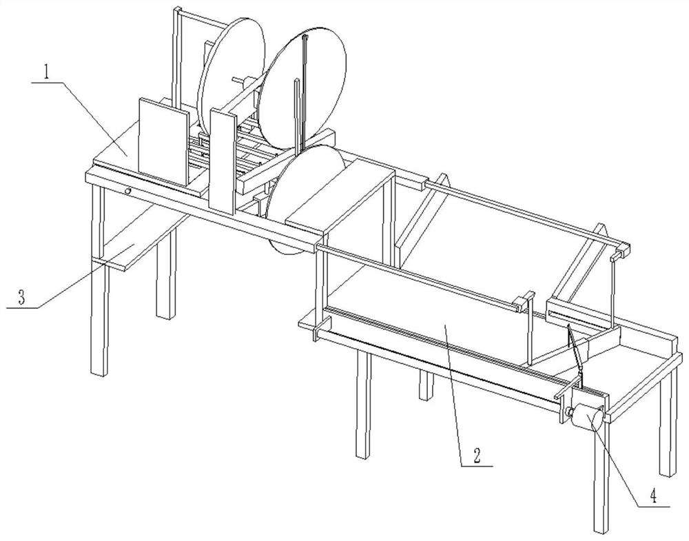
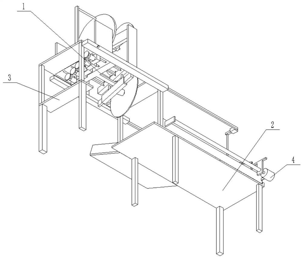
[0033] Specific implementation mode one: as Figure 1-13 As shown, this embodiment describes a multi-angle metal pipe cutting device, including a cutting device 1, a feeding device 2, a support plate 3 and a power device 4; the power device 4 is fixedly connected to the side of the feeding device 2; The cutting device 1 is fixedly connected to the support plate 3 and the upper end of the feeding device 2 , and there is a gap between the support plate 3 and the feeding device 2 . The lower ends of the bottom plate 21 and the support plate 3 are provided with a support frame, and the support frame is fixedly connected to the ground.
specific Embodiment approach 2
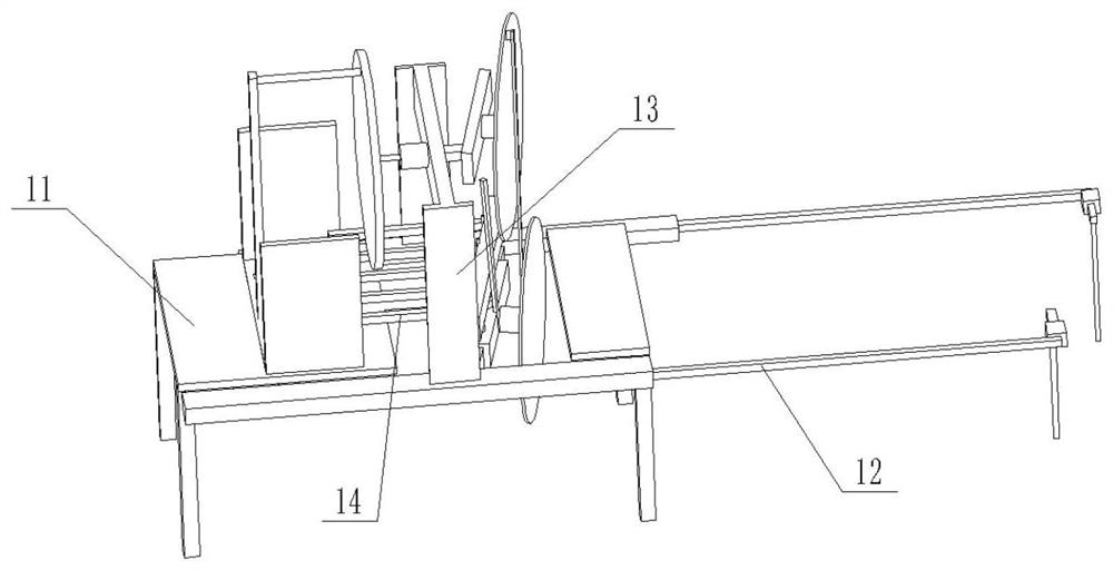
[0034] Specific implementation mode two: as Figure 1-13 As shown, this embodiment is a further description of Embodiment 1. The cutting device 1 includes a bracket 11, a linkage device 12, a supporting device 13 and a connecting device 14; the side of the bracket 11 is fixedly connected with a linkage device 12; the support device 13 is fixedly connected to the upper end of the linkage device 12, and the support device 13 is located above the support 11; one end of the connection device 14 is hinged to the linkage device 12, and the other end of the connection device 14 is connected to the support 11 Slip fit.
specific Embodiment approach 3
[0035] Specific implementation mode three: as Figure 1-13 As shown, this embodiment is a further description of specific embodiment 1. The bracket 11 includes a plurality of struts 1101, a horizontal plate I 1102, a sliding plate 1103, two limiting plates 1104, a connecting rod 1106 and a horizontal plate II 1108; The plurality of struts 1101 are fixedly connected to the lower ends of the horizontal plate I1102 and the horizontal plate II1108; the horizontal plate I1102 is provided with a rectangular through hole; the sliding plate 1103 is slidingly fitted with the rectangular through hole on the horizontal plate I1102, and the sliding plate The upper end of 1103 is symmetrically fixedly connected with two limiting plates 1104. When the sliding plate 1103 slides downward, the two limiting plates 1104 respectively contact the inner wall of the rectangular through hole; one end of the connecting rod 1106 is fixedly connected to the horizontal plate I 1102 On the side, the other...
PUM
 Abstract
Description
Claims
Application Information