Bridge incremental launching construction technology

A technology for jacking construction and bridges, applied in bridges, bridge parts, bridge materials, etc., can solve problems such as obstruction of river and road traffic, inconvenience for residents to travel, etc., to improve jacking accuracy, fast construction progress, and simple construction process. Effect

Inactive Publication Date: 2021-08-31
GUANGXI BEITOU HIGHWAY CONSTR & INVESTMENT GRP CO LTD +2
View PDF8 Cites 0 Cited by
  • Summary
  • Abstract
  • Description
  • Claims
  • Application Information

AI Technical Summary

Problems solved by technology

[0002] In the process of bridge construction, it is often necessary to cross rivers or roads. During the construction of bridges, the passage of rivers and roads will be hindered to a certain extent, which will cause inconvenience to residents. Construction method with less impact on traffic

Method used


Image

  • Bridge incremental launching construction technology
  • Bridge incremental launching construction technology
  • Bridge incremental launching construction technology

Examples


Embodiment 1

[0048] A bridge for the new bridge, the bridge is a river located in Alluvial terraces topography, elevation between 146.9-150.4m. Now the bridge across a river, a width of 40m during drilling construction, water depth of about 5m. The present embodiment is path and channel centerline intersection angle 98 °, the orthogonal bridge design. The main bridge 1 × 60m corrugated steel webs prestressed concrete box girder, bridge approach using 3 × 30m Fabricated Prestressed concrete T beam, with a total of two full bridge. Main bridge deck from the bottom layer of a flexible waterproof and 10cm thick asphalt concrete pavement, bridge deck slope bidirectional 2%; and on both sides of a first abutment provided at the pier D80 expansion joints, main bridge pot bearings, bridge approach using plate bearing pier pile using column, column diameter 1.8m, 2.0m diameter pile, pier foundation embedded using rock foundation, abutment gravity U-station, base expanded. Will now be changed to the mai...

Embodiment 2

[0053] Status as a high-speed two-way 24.5m four-lane highway, there are eight-lane widening of the requirements according to the relevant departments of planning, after widening roadbed section is 43.25m, pass clearance of not less than 6m. The present embodiment the high speed line intersecting angle is 90 °, the orthogonal design bridge, simply supported span of 60 meters across the bridge structure, the bridge is oriented by the layer of a flexible waterproof and 10cm thick asphalt concrete pavement, bridge deck bidirectional 2 % slope, abutments are located on both sides of D80 expansion joints, the use of pot bearings, bridge abutment using gravity U station, broaden the base. Bridge superstructure original design double steel box - concrete composite beams (double channel steel box composite beam), steel specimens of single construction program - a combination of a span of the lifting mixed, so a greater impact on existing highway construction program, in order to ensure th...


PUM


Abstract

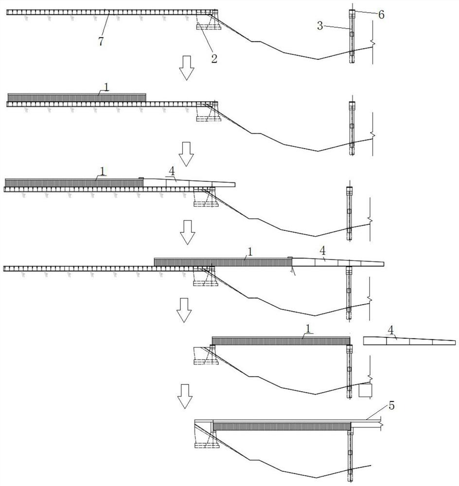
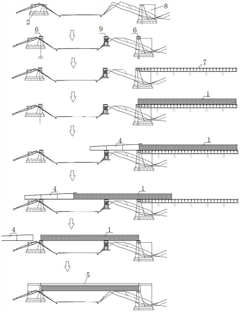
The invention discloses a bridge incremental launching construction process which comprises the following steps: step 1, construction preparation: constructing supporting parts on two sides of a bridge, respectively arranging slideways on the two supporting parts, arranging incremental launching equipment at the slideway of the supporting part on one side, and prefabricating and assembling a beam body on the outer side of the supporting part provided with the incremental launching equipment, and arranging the bottom part on the slideway on the outer side of the supporting part, wherein the beam body assembling process comprises the steps of manufacturing and transporting the corrugated steel web, connecting the corrugated steel web with the concrete top plate and the concrete bottom plate, conducting prestress construction, conducting steel bar construction and conducting concrete box beam cast-in-place construction; step 2, symmetrically installing deviation rectifying devices on the two sides of the beam body; step 3, installing a guide beam; step 4, pushing the beam body to the designed position; step 5, dismantling the guide beam, controlling the beam body to fall, and enabling the two ends of the beam body to be fixed to the supporting parts on the two sides; and step 6, installing guardrails, laying a bridge deck and completing overall construction of the bridge. In the bridge construction process, the influence on passing of the road surface or the river channel under the bridge is small, and continuous crossing construction can be achieved.

Description

Technical field [0001] The present invention relates to the field of bridge construction, particularly to a bridge construction technology of pushing. Background technique [0002] In the bridge construction process, often need to cross a river or road and bridge construction, road and river traffic will be subject to certain obstacles, thereby causing inconvenience to the residents travel, and therefore need for a construction process, on the road or the river under the bridge prevailing low-impact construction methods. Inventive content [0003] Object of the present invention is to provide a pushing bridge construction technology to solve the problem of the prior art, so that the bridge construction process, little effect on the access road or river bridges. [0004] In order to achieve the above object, the present invention provides the following scenarios: [0005] The present invention provides a push bridge construction technology, comprising the steps of: [0006] Step ...

Claims


Application Information

Patent Timeline
Patent Type & Authority Applications(China)
IPC IPC(8): E01D21/00E01D19/00E01D19/02E01D2/04E01D101/28
CPCE01D21/00E01D19/00E01D19/02E01D2/04E01D2101/28
Inventor 张云罗婷倚刘玉擎唐亚森周晓蓉叶源杨明梁夏陈三喜
Owner GUANGXI BEITOU HIGHWAY CONSTR & INVESTMENT GRP CO LTD
Why Eureka
Try Eureka