Steel bar mechanical connecting device and method

A technology of mechanical connection and reinforcement, applied in the direction of structural elements, building components, building reinforcements, etc., can solve the problems of unqualified connection performance, size error, connection thread damage, etc., to save assembly process and assembly time, reduce the number of , reduce the effect of deformation

Pending Publication Date: 2021-08-31
徐瑞榕 +1
View PDF0 Cites 0 Cited by
  • Summary
  • Abstract
  • Description
  • Claims
  • Application Information

AI Technical Summary

Problems solved by technology

[0007] 2) The "reinforcement thread trajectory" at both ends of the straight thread joint connection does not coincide, so that the effective connection of the reinforcement cannot be realized: the size error caused by the prefabrication, installation and connection of the parts, it is difficult to ensure that the "reinforcement thread trajectory" at both ends of each joint connection can be correct. coincide
At present, straight threaded joints are used in the connection of basic reinforcement cages. Even if the "pre-assembled" method is adopted on the ground, there are still many joints connected with such problems. Even if the connection torque is increased (may increase several times to 10 times , it seems that the sleeve is connected in place, in fact, the inner connecting thread has been greatly damaged, and the connection performance cannot be qualified

Method used


Image

  • Steel bar mechanical connecting device and method
  • Steel bar mechanical connecting device and method
  • Steel bar mechanical connecting device and method

Examples


Embodiment 1

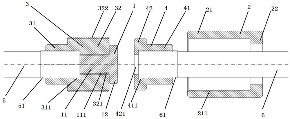
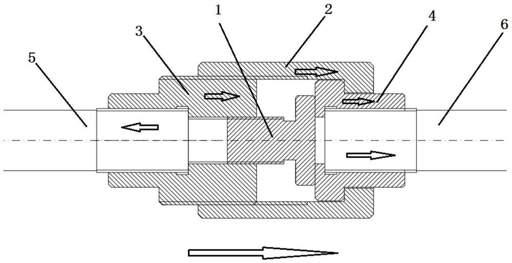
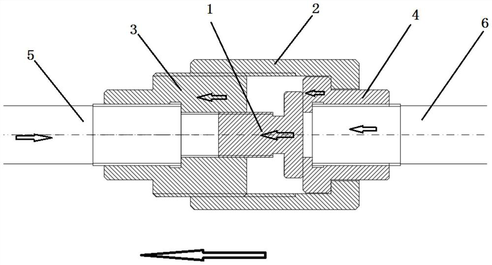
[0049] Such as Figure 1-3 As shown, a mechanical connection device for steel bars is used to connect the first steel bar 5 and the second steel bar 6, including a pressure-bearing inner push rod 1 and an outer screw sleeve 2; the end of the first steel bar 5 is provided with an outer diameter larger than The first connecting part 3 of the first steel bar 5, the end of the second steel bar 6 is provided with a second connecting part 4 whose outer diameter is larger than that of the second steel bar 6, and the pressure-bearing inner push rod 1 includes a screw thread The screw joint section 11 and the top joint section 12, the end of the first connecting part 3 is provided with an axial pressure-bearing internal thread hole 321 matched with the pressure-bearing external thread 111 of the screw joint section 11, the The jacking section 12 is jacked to the end of the second connecting member 4 by adjusting the length of the threaded joint section 11 screwed to the axial pressure-...

Embodiment 2

[0063] The difference from the above-mentioned embodiment is that, if Figure 4 As shown, the connection between the first connecting member 3 and the second connecting member 4 and the first steel bar 5 and the second steel bar 6 can be replaced by welding connection or adhesive connection. Specifically, the first steel bar connection end 31 is a solid end, and is fixed to the end of the first steel bar 5 by welding or bonding. The second connection part 4 can adopt the solution of Embodiment 1, and can also preferably be the following solution, the second steel bar connection end 41 is a solid end and is fixed to the second steel bar 6 by welding or bonding. Ends.

[0064] As preferred, such as Figure 5 As shown, the first steel bar connecting end 31 is a solid end, and is fixed to the end of the section steel 7 by welding or bonding.

Embodiment 3

[0066] The difference from the above-mentioned embodiment is that, if Image 6As shown, the connection method between the first connecting part 3 and the second connecting part 4 and the first steel bar 5 and the second steel bar 6 can be replaced by a steel bar upsetting type. Specifically, the first connecting part 3 includes a first end portion 52 formed after the first steel bar 5 is upset, and the axial pressure-bearing internal thread hole 321 and the first external thread 322 are provided on the The first end portion 52 . The second connection part 4 can adopt the solution of embodiment 1 or 2, and can also preferably be the following solution, the second connection part 4 includes the second end 62 formed after the second steel bar 6 is upset, so The second end portion 62 is provided with a boss 621 whose diameter is smaller than the inner diameter of the straight thread sleeve 21 and larger than the diameter of the second steel bar and the diameter of the inner hole ...


PUM


Abstract

The invention discloses a steel bar mechanical connecting device and method. According to the steel bar mechanical connecting device and method, a connecting gap between a first steel bar and a second steel bar is eliminated through a pressure-bearing inner ejector rod, so that deformation of a connector under large pressure is easier to reduce, meanwhile direct or indirect connection of the first steel bar and the second steel bar is achieved through an outer threaded sleeve, therefore, the connection is easy without being limited by trouble of difficulty in connection when trajectory lines are not coincident. Through cooperation of the pressure-bearing inner ejector rod and the outer threaded sleeve, mechanical connection between two connecting steel bars with a certain gap in the axial position can be achieved, residual deformation of the connector can be controlled within a small range, and after specified high-stress and large-deformation repeated pulling and pressing circulation, the ultimate tensile strength and deformation performance of the steel bar can still meet regulations in high-stress repeated tension and compression and large-deformation repeated tension and compression in the industrial standard JGJ 107 General Technical Regulations for Mechanical Connection of Reinforcing Steel bars. Steel bar mechanical connection construction under a vertical narrow gap connection working condition of a prefabricated structure is facilitated, and qualified rate of the steel bar mechanical connection device is increased.

Description

technical field [0001] The invention relates to a steel bar mechanical connection device and method, belonging to the technical field of construction engineering steel bar mechanical connection. Background technique [0002] At present, the country is vigorously promoting the industrialization of construction. Construction industrialization refers to the replacement of scattered, low-level and inefficient handicraft production methods in the traditional construction industry through modern manufacturing, transportation, installation and scientifically managed production methods. Its main symbols are standardization of architectural design, factory production of components, mechanization of construction and scientific organization and management. Among them, all standardized accessories and modular reinforced concrete structures need to be assembled through mechanical connection of steel bars. Therefore, in the industrialization technology of steel bar engineering, the mech...

Claims


Application Information

Patent Timeline
Patent Type & Authority Applications(China)
IPC IPC(8): E04C5/16
CPCE04C5/165
Inventor 徐瑞榕王圣任
Owner 徐瑞榕
Why Eureka
Try Eureka