A self-priming centrifugal pump

A self-priming centrifugal pump and pump body technology, applied in the field of centrifugal pumps, can solve the problems of reduced service life, high noise, and large impact on the internal parts of the pump body, so as to accelerate the separation of water and gas, reduce wear, and reduce cavitation. effect of the phenomenon

Active Publication Date: 2022-04-15
LEO GRP ZHEJIANG PUMP CO LTD
View PDF4 Cites 0 Cited by
  • Summary
  • Abstract
  • Description
  • Claims
  • Application Information

AI Technical Summary

Problems solved by technology

Wherein a liquid storage chamber is provided between the pressurization chamber and the liquid inlet, and the self-priming pump also includes a communication pipe with an inlet end and an outlet end, the communication pipe is installed on the pump casing, and is located on the Between the pressurization chamber and the liquid inlet, the inlet end of the communication pipe is connected to the liquid inlet, and in multiple sections in the direction perpendicular to the flow direction of the medium, the communication pipe has at least One section is higher than the lowest point of the suction port of the impeller, and at least one section is located above the inlet end; but the above-mentioned patent still has defects, the connecting pipe at the inlet end is bent, so when connected to the external water pipe, the external The part where the water pipe and the connecting pipe are combined is curved. During the start-up process of the water pump, the water flow hits the curved part, which will easily lead to a greater impact on the curved part and greater wear and tear, reducing the service life and easily causing the connection part to fall off. , which affects the normal operation of the centrifugal pump; and under the action of the impeller, the water flow inside the pump body is faster, which generates greater noise and has a greater impact on the internal components of the pump body, which is likely to cause excessive wear of the centrifugal pump and affect Centrifugal pump service life

Method used


Image

  • A self-priming centrifugal pump
  • A self-priming centrifugal pump
  • A self-priming centrifugal pump

Examples


Embodiment approach

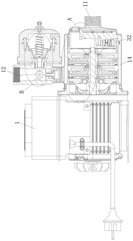
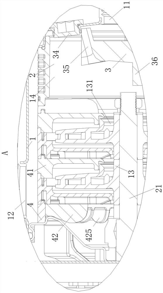
[0034]As a specific embodiment of the present invention, the guide body includes a general guide body 41 and a terminal guide body 42, and the general guide body 41 is installed on the rotating shaft 21 at the gap between the impellers 13; The guide body 42 is installed on the rotating shaft 21, and is located on the side of the impeller 13 away from the water inlet 11, and the end guide body 42 is located below the water outlet 12; the end guide body 42 includes a guide ring 421 and a guide plate 422, the The drainage ring 421 is nested on the side wall of the water inlet channel 2, and the inner surface of the drainage ring 421 is fixedly connected with a drainage plate 422, and the junction of the surface of the drainage plate 422 facing the impeller 13 and the inner surface of the drainage ring 421 is evenly arranged. A plurality of water outlet grooves 423 ; a No. 1 through hole 424 is provided in the middle of the diversion plate 422 , and the rotating shaft 21 passes thr...


PUM


Abstract

The invention belongs to the technical field of centrifugal pumps, in particular to a self-priming centrifugal pump, which includes a pump body, a water inlet, a water outlet, an impeller, a water inlet channel, an inlet bracket assembly, a guide body assembly and a pressure supplement assembly; There is a water inlet channel inside the pump body, one end of the water inlet channel communicates with the outside world through a horizontally arranged water inlet, and the other end communicates with the outside world through a vertically arranged water outlet; The water level prevents the injected start-up water from flowing out of the water outlet, which affects the start-up of the centrifugal pump, and ensures that the start-up water fills the pump body smoothly; the impeller stops rotating, and the remaining water inside the pump body is affected by the water baffle due to the function of the water baffle. The barrier prevents it from flowing out through the water inlet, and saves it inside the pump body as the starting water for the next start of the centrifugal pump, reducing the preparation work before the next start of the centrifugal pump and making the start of the centrifugal pump smoother.

Description

technical field [0001] The invention belongs to the technical field of centrifugal pumps, in particular to a self-priming centrifugal pump. Background technique [0002] Centrifugal pumps work by rotating the impeller to cause the water to move centrifugally. Before starting the pump, the pump casing and the suction pipe must be filled with water, and then the motor is started to drive the impeller and the water to rotate at a high speed. The water undergoes centrifugal motion and is thrown to the outer edge of the impeller, and flows through the volute pump casing. The pressure water pipeline flowing into the water pump. Self-priming centrifugal pump is a kind of centrifugal pump. Refers to the centrifugal pump that can automatically pump out the gas in the suction pipe and normally deliver the liquid without priming the pump when it is started again, except for the pump that needs to be primed before the first start. The pump is equipped with a suction chamber at the in...

Claims


Application Information

Patent Timeline
Patent Type & Authority Patents(China)
IPC IPC(8): F04D13/06F04D9/02F04D29/44F04D29/66
CPCF04D13/06F04D9/02F04D29/445F04D29/669
Inventor 颜土富颜成刚林荣张逸金士海
Owner LEO GRP ZHEJIANG PUMP CO LTD
Why Eureka
Try Eureka