
Pipe joint assembly for fluid multi-parameter measurement

A multi-parameter, pipe joint technology, applied in the application of optical methods for fluid pressure measurement, pipe/pipe joint/pipe fitting, temperature measurement of moving fluids, etc., can solve problems such as hydraulic pipeline leakage

Pending Publication Date: 2021-08-31
潍坊嘉腾液压技术有限公司
View PDF0 Cites 2 Cited by
  • Summary
  • Abstract
  • Description
  • Claims
  • Application Information

AI Technical Summary

Problems solved by technology

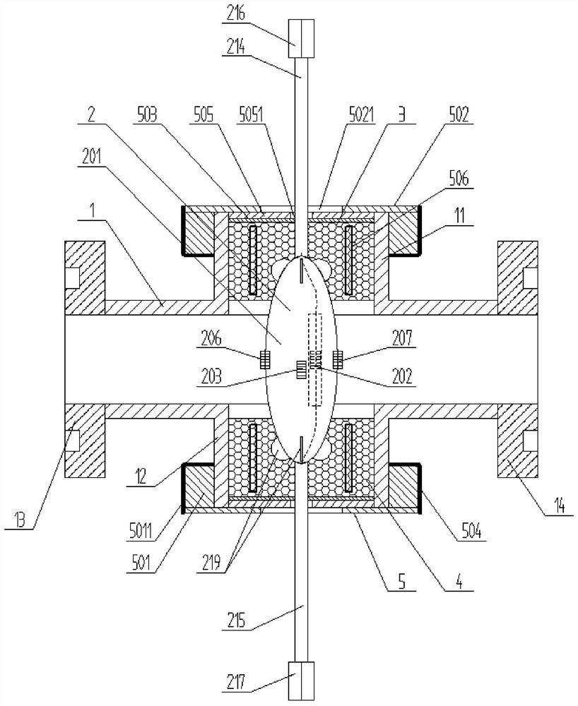
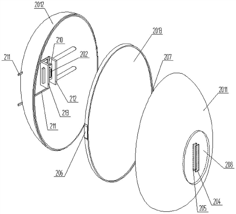
[0005] In order to solve the above-mentioned problems in the prior art, that is, in order to solve the problem in the prior art that it is necessary to set multiple detection points on the hydraulic pipeline to install temperature, pressure and flow sensors at the same time, thereby increasing the risk of leakage of the hydraulic pipeline, this paper The disclosure provides a pipe joint assembly for multi-parameter measurement of fluids. The pipe joint assembly for multi-parameter measurement of fluids includes a four-way pipe joint and a four-way pipe joint arranged on the aforementioned four-way pipe. The composite sensor in the joint, the aforementioned four-way pipe joint includes the first joint, the second joint and the third joint and the fourth joint for fixing the aforementioned composite sensor and optical cable, and the third joint and the fourth joint of the transmission pipeline liquid; sensor, fiber grating temperature and pressure sensor, fiber grating pressure pulsation sensor, first fiber grating flow velocity sensor and second fiber grating flow velocity sensor, and an optical cable composed of multiple optical fibers: one end of the aforementioned housing is embedded in the aforementioned first connector and connected to the aforementioned first fiber grating velocity sensor A joint is fixedly connected, and the other end of the housing is embedded in the second joint and is fixedly connected with the second joint; each of the optical fibers in the optical cable composed of multiple optical fibers is recorded with a grating, and thus forms the temperature of the optical fiber grating. Sensor, aforementioned fiber Bragg grating temperature and pressure sensor or aforementioned fiber Bragg grating pressure pulsation sensor, first fiber Bragg grating flow velocity sensor and second fiber Bragg grating flow velocity sensor; the aforementioned optical cables at both ends of the aforementioned housing run through the sealed connection of the aforementioned first joint and the aforementioned second joint Part; the aforementioned fiber grating temperature sensor is arranged in the inside of the aforementioned housing, and can detect the temperature of the liquid in the aforementioned four-way pipe joint; the aforementioned optical fiber grating temperature and pressure sensor is arranged on the aforementioned housing, and can detect The comprehensive data of the temperature and pressure of the liquid; the aforementioned fiber grating pressure pulsation sensor is arranged on the aforementioned casing, and can detect the pressure fluctuation of the liquid in the aforementioned four-way pipe joint

Method used


Image

  • Pipe joint assembly for fluid multi-parameter measurement
  • Pipe joint assembly for fluid multi-parameter measurement
  • Pipe joint assembly for fluid multi-parameter measurement

Examples


Embodiment Construction

[0036] Those skilled in the art should understand that the embodiments described below are only preferred embodiments of the present disclosure, and the preferred embodiments are intended to explain the technical principles of the present disclosure, and do not mean that the technical principles of the present disclosure can only be passed through Only the preferred embodiment can be realized, so the preferred embodiment cannot limit the protection scope of the present disclosure. Based on the preferred embodiments provided in the present disclosure, all other embodiments obtained by persons of ordinary skill in the art without making creative efforts should still fall within the protection scope of the present disclosure.

[0037] It should be noted that in the description of the present disclosure, the terms "center", "upper", "lower", "top", "bottom", "left", "right", "vertical", "horizontal", " Terms indicating directions or positional relationships such as "inner", "outer...


PUM


Abstract

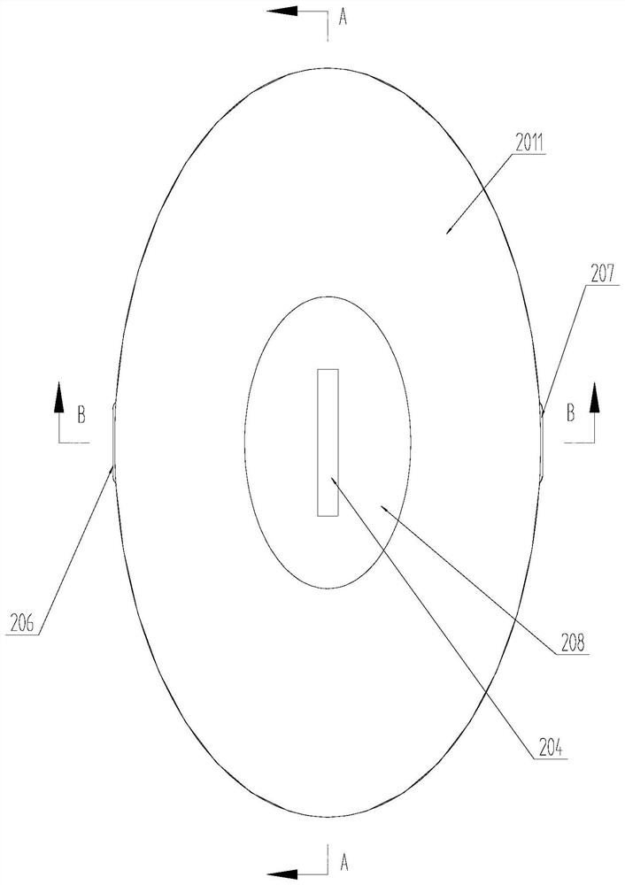
The invention provides a pipe joint assembly for fluid multi-parameter measurement. The pipe joint assembly for fluid multi-parameter measurement comprises a four-way pipe joint and a composite sensor arranged in the four-way pipe joint, wherein the four-way pipe joint comprises a first joint and a second joint which are used for fixing the composite sensor and an optical cable, and a third joint and a fourth joint which are used for transmitting pipeline liquid; the composite sensor comprises a shell, a fiber bragg grating temperature sensor arranged in the shell, and a fiber bragg grating temperature pressure sensor, a fiber bragg grating pressure pulsation sensor, a first fiber bragg grating flow velocity sensor and a second fiber bragg grating flow velocity sensor which are arranged on the shell; one end of the shell is embedded into the first joint and fixedly connected with the first joint, and the other end of the shell is embedded into the second joint and fixedly connected with the second joint; and the optical cable extending out of the composite sensor is led out from the sealing connection part of the first joint and the second joint. According to the pipe joint assembly for fluid multi-parameter measurement provided by the invention, hydraulic multi-parameter detection can be effectively enhanced, the number of measuring points is reduced, and the risk of hydraulic pipeline leakage is reduced.

Description

technical field [0001] The disclosure belongs to the technical field of fluid equipment, and specifically provides a pipe joint assembly for multi-parameter measurement of fluid. Background technique [0002] In the hydraulic transmission system, the flow rate (kinetic energy) of the medium is low, and the potential energy generated is relatively low, which can be ignored, and the power is transmitted only by the pressure of the working medium, which is the so-called hydrostatic transmission. With the application of artificial intelligence in construction machinery and other fields, as a "small but powerful" hydraulic system, it can amplify electronic information into mechanical actions through the hydraulic system. Therefore, the hydraulic system is an important intermediate link in the operation of intelligent machinery. In order to ensure the normal operation of the hydraulic system, it is usually necessary to monitor the operating parameters of the hydraulic system in r...

Claims


Application Information

Patent Timeline
IPC IPC(8): F16L23/00F16L15/08F15B19/00G01K11/3206G01K13/02G01K1/08G01K1/14G01K1/16G01L11/02G01L19/00G01L19/06G01L19/14G01P5/14G01P1/02G01P13/00G01F1/34
CPCF15B19/00F16L15/08F16L23/006G01F1/34G01K1/08G01K1/14G01K1/16G01K11/32G01K13/02G01L11/025G01L19/0092G01L19/0609G01L19/069G01L19/143G01L19/144G01P1/026G01P5/14G01P13/0066
Inventor 黄爱武王洪涛程永革
Owner 潍坊嘉腾液压技术有限公司
Learn More