Pipeline water leakage detection system in pipe gallery
A technology of detection system and inner pipeline, applied in pipeline system, cable installation in ground conduit, gas/liquid distribution and storage, etc., can solve the problem of lack of effective monitoring of water leakage in underground pipe gallery
- Summary
- Abstract
- Description
- Claims
- Application Information
AI Technical Summary
Problems solved by technology
Method used
Image
Examples
Embodiment 1
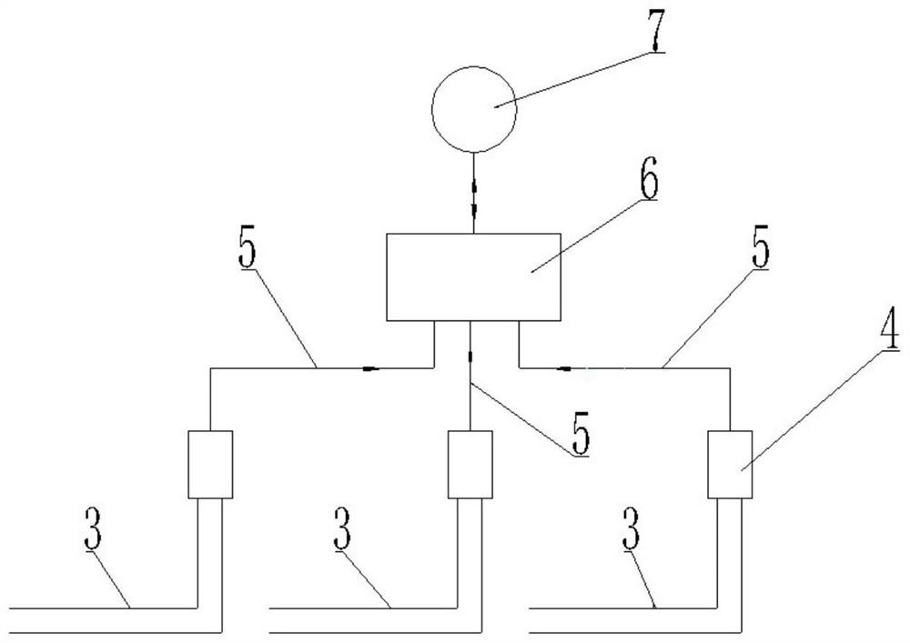
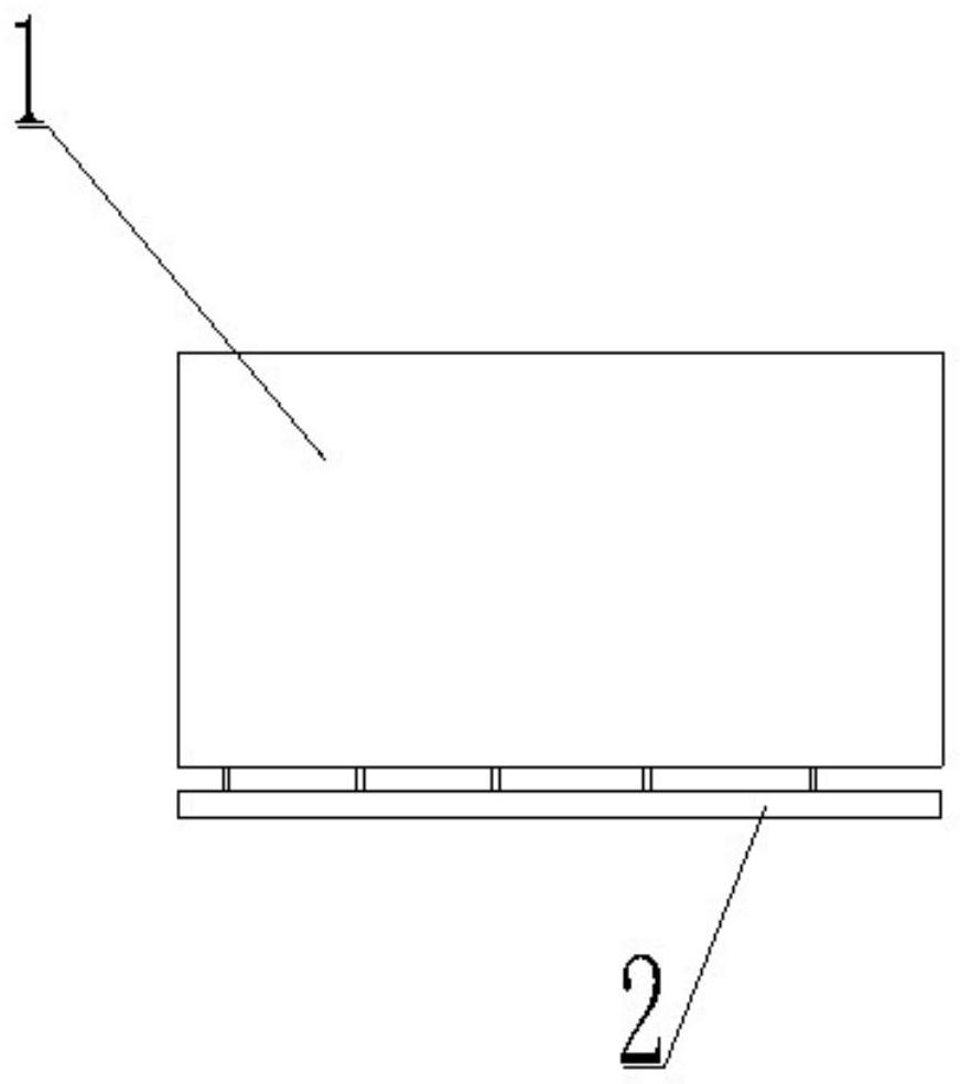
[0036] A pipeline leakage detection system in a pipeline gallery (see attached figure 1 ), including two parallel wires 3 and a server 6, the two parallel wires 3 are laid in multiple groups along the pipe gallery, and are respectively laid under the water pipe 1 in the pipe gallery, and the two wires 3 of each group are connected to a data On the collector 4, each data collector 4 is connected to the server 6 through a network cable 5, 4G or 5G communication; the data collector 4 is provided with a power supply unit for supplying power to the wire 3, a detection unit for detecting whether the two wires are short-circuited, and a communication with The communication unit that the server 6 interacts; the server 6 is also connected to the control center 7 and / or the mobile phone, and the mobile phone is installed with an APP with a control function. .
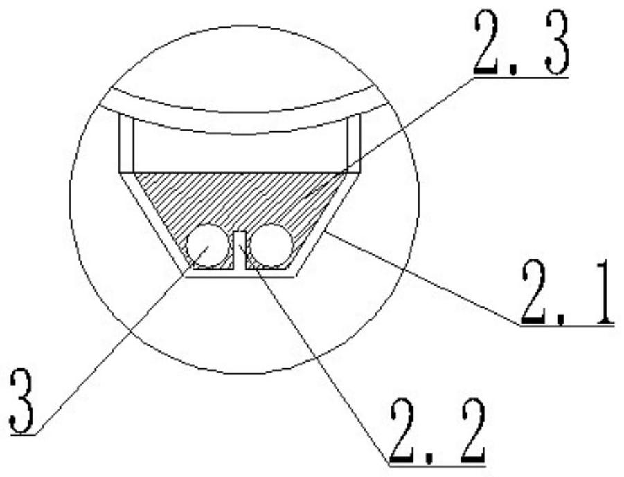
[0037] Wherein, the wire is laid in the wire groove 2 (see Figure 2-5 ), the wire groove adopts an insulating material; the ...
Embodiment 2
[0042] On the basis of Example 1, the water-soluble filler 2.3 is filled in the wire groove 2 (see figure 2 , 5 ), the water-soluble filler 2.3 is composed of the following parts by weight: 40-60 parts of soluble starch, 10-15 parts of sodium chloride, 5-10 parts of polyvinylpyrrolidone, 3-5 parts of polystyrene microspheres and 3-5 parts of xanthan gum; the filling method of the water-soluble filler is as follows: weigh each component by weight, add the soluble starch to water at a constant temperature of 80°C in batches, stir until completely dissolved, add chlorine After dissolving the sodium, continue to stir until completely dissolved, add polyvinylpyrrolidone and polystyrene microsphere xanthan gum, stir evenly, pour into the wire groove 2, compact and smooth it with a scraper, and let it dry naturally.
Embodiment 3
[0044] On the basis of embodiment 1, the described wire is laid on the ground and reserves the wire groove 21 (referring to Figure 5 ), the waterproof paint layer 2.4 is brushed in the reserved wire groove 21, the neutral plate 2.21 is arranged at the bottom of the reserved wire groove 21, and the height of the neutral plate 2.21 is greater than the diameter of the wire 3 and less than the side wall height of the reserved wire groove 21;
[0045] Reserve the wire groove 21 to shop and fill the water-based paint 2.3, lay the hydrolyzed plastic film 2.5 on the top surface of the water-based paint 2.3, and lay the isolation net 2.6 at the opening of the reserved wire groove 21 above the hydrolyzed plastic film 2.5.
PUM
| Property | Measurement | Unit |
|---|---|---|
| length | aaaaa | aaaaa |
Abstract
Description
Claims
Application Information
 - R&D
- Intellectual Property
- Life Sciences
- Materials
- Tech Scout
- Unparalleled Data Quality
- Higher Quality Content
- 60% Fewer Hallucinations
Browse by: Latest US Patents, China's latest patents, Technical Efficacy Thesaurus, Application Domain, Technology Topic, Popular Technical Reports.
© 2025 PatSnap. All rights reserved.Legal|Privacy policy|Modern Slavery Act Transparency Statement|Sitemap|About US| Contact US: help@patsnap.com


