Optical delay measurement method and device based on pulsed light modulation

A time-delay measurement and pulsed light technology, applied in the field of optical measurement, can solve problems such as short measurement range, limited measurement speed, and high device requirements, and achieve stable and reliable measurement, error avoidance, and high system stability.

Active Publication Date: 2022-04-22
NANJING UNIV OF AERONAUTICS & ASTRONAUTICS
View PDF6 Cites 0 Cited by
  • Summary
  • Abstract
  • Description
  • Claims
  • Application Information

AI Technical Summary

Problems solved by technology

[0004] The phase calculation method uses the phase change during link transmission to solve the optical delay, and the accuracy is high, usually at the submillimeter level. However, in order to ensure the measurement accuracy, it is often necessary to measure the phase of the higher frequency signal. Using frequency conversion, it is easy to introduce additional noise and cause errors
In addition, in order to obtain the ambiguity of the entire cycle of the high-frequency signal, it is necessary to sweep the frequency within a certain range to obtain the phases of multiple frequency points, which not only increases the system cost and complexity, but also limits the measurement speed of this method
[0005] To sum up, the existing technology has the following disadvantages: (1) the pulse method has poor precision, only at the meter level; (2) the sweeping interferometry has high requirements on devices, high cost and short measurement range; (3) the phase-inference method Frequency sweep is required, the measurement speed is limited and high-frequency phase detection is easy to introduce errors

Method used


Image

  • Optical delay measurement method and device based on pulsed light modulation
  • Optical delay measurement method and device based on pulsed light modulation
  • Optical delay measurement method and device based on pulsed light modulation

Examples


Embodiment Construction

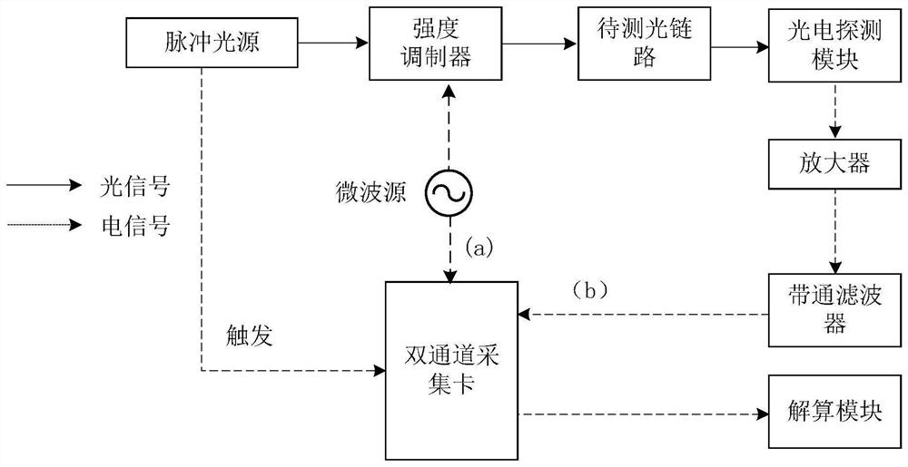
[0033] Aiming at the defect that the existing interpolation ranging technology requires frequency sweeping and slow measurement speed, the solution idea of ​​the present invention is to abandon the way of sweeping multiple frequency points to solve the whole circle ambiguity, and use pulsed light as a carrier to modulate a single-frequency signal. Digital sampling directly obtains the time difference between pulse transmission and reception, and obtains a rough measurement of time delay; at the same time, the phase difference between the measurement path and the reference path is obtained by using the collected digital signal processing; finally, the phase of the modulated signal is calculated by using the rough measurement of time delay The entire cycle fuzzy value, combined with the two-way phase difference, and then solve the optical delay of the link to be tested.

[0034] The optical delay measurement method based on pulsed light modulation proposed by the present inventio...


PUM


Abstract

The invention discloses an optical delay measurement method based on pulsed light modulation, which uses a single-frequency microwave signal to perform intensity modulation on the optical pulse signal, and uses the generated light-borne microwave signal to detect the optical link to be measured; the detection optical signal Perform photoelectric conversion, and extract the same-frequency component of the single-frequency microwave signal from the converted electrical signal; simultaneously digitally sample the single-frequency microwave signal and the same-frequency component of the single-frequency microwave signal within the pulse width of the optical pulse signal , and the phase difference between the two is obtained in the digital domain; the time between the sending moment of the optical pulse signal and the sampling moment is taken as the rough measurement value of the optical delay of the optical link to be tested, and based on the rough measurement value of the optical delay The whole cycle ambiguity is solved, and then the precise optical delay of the optical link to be tested is obtained through calculation. The invention also discloses an optical delay measurement device based on pulsed light modulation. The invention has the advantages of fast measurement speed, simple structure, low realization cost and less susceptible to environmental influence.

Description

technical field [0001] The invention relates to an optical time delay measurement method, which belongs to the technical field of optical measurement. Background technique [0002] Delay is a basic parameter in signal generation, transmission, and control. With the rapid development of optical electronic information systems, the bearer network, core network, and backbone network that constitute this type of system are composed of various optical link products. All kinds of optical link products need precise and high-speed measurement of optical link delay in the whole process of production, application and maintenance. Fast and stable measurement of delay in optical links has become the key to the research and application of high-performance information systems such as 5G communications, optically controlled phased arrays, and distributed radar networks. [0003] The commonly used optical delay measurement methods mainly include pulse method, frequency sweep interferometry ...

Claims


Application Information

Patent Timeline
Patent Type & Authority Patents(China)
IPC IPC(8): H04B10/079H04B10/524
CPCH04B10/0795H04B10/524
Inventor 李树鹏潘时龙刘熙王祥传汤晓虎王立晗陈旭峰
Owner NANJING UNIV OF AERONAUTICS & ASTRONAUTICS
Why Eureka
Try Eureka