Nasal cavity washing equipment
A technique for nasal irrigation and equipment, applied in bathing devices, physical therapy, etc., can solve the problems of troublesome washing, people choking, improper force control, etc., and achieve the effect of convenient operation and reduced labor intensity
- Summary
- Abstract
- Description
- Claims
- Application Information
AI Technical Summary
Problems solved by technology
Method used
Image
Examples
Embodiment 1
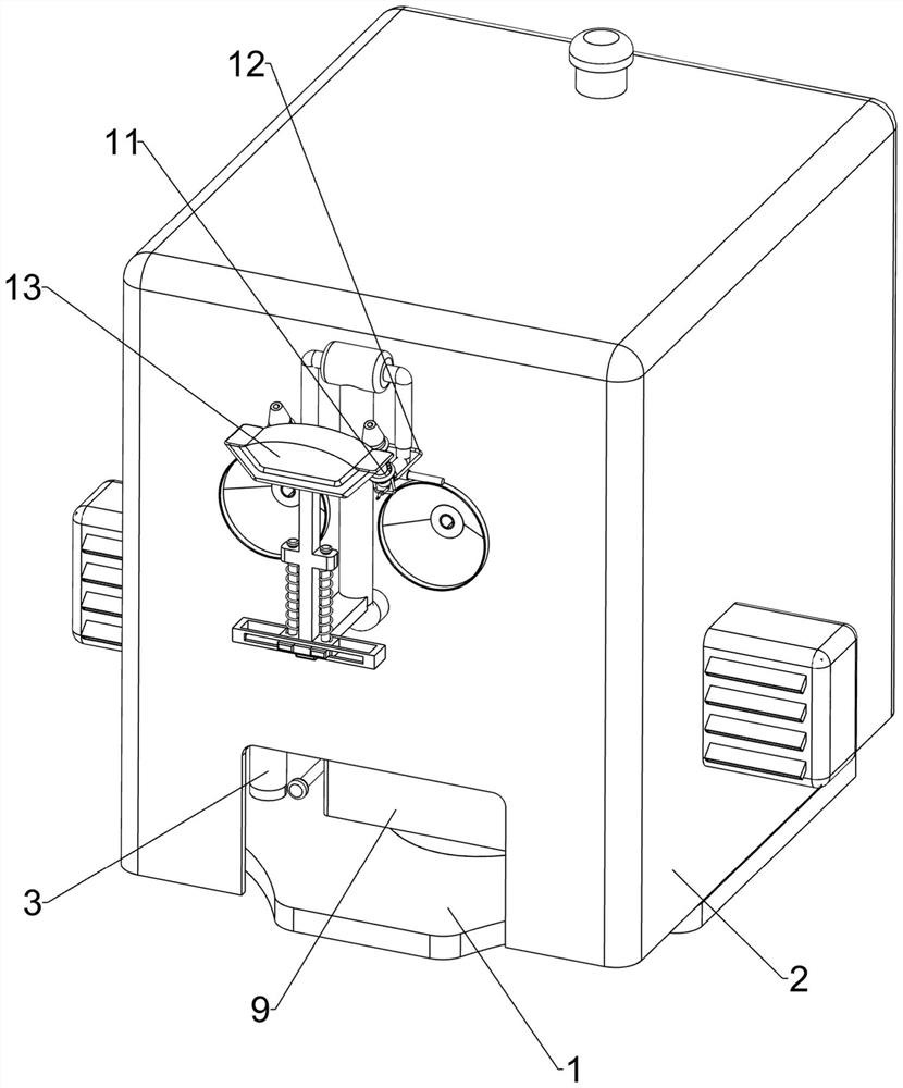
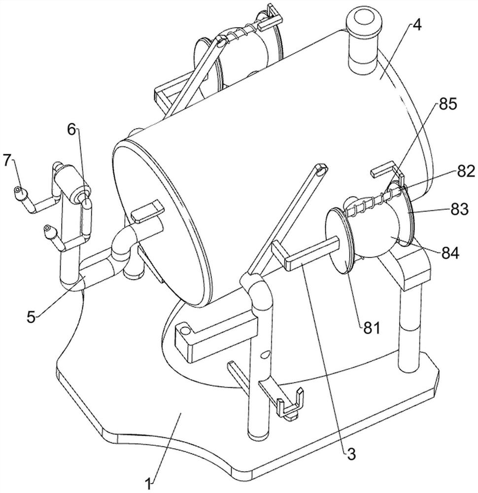
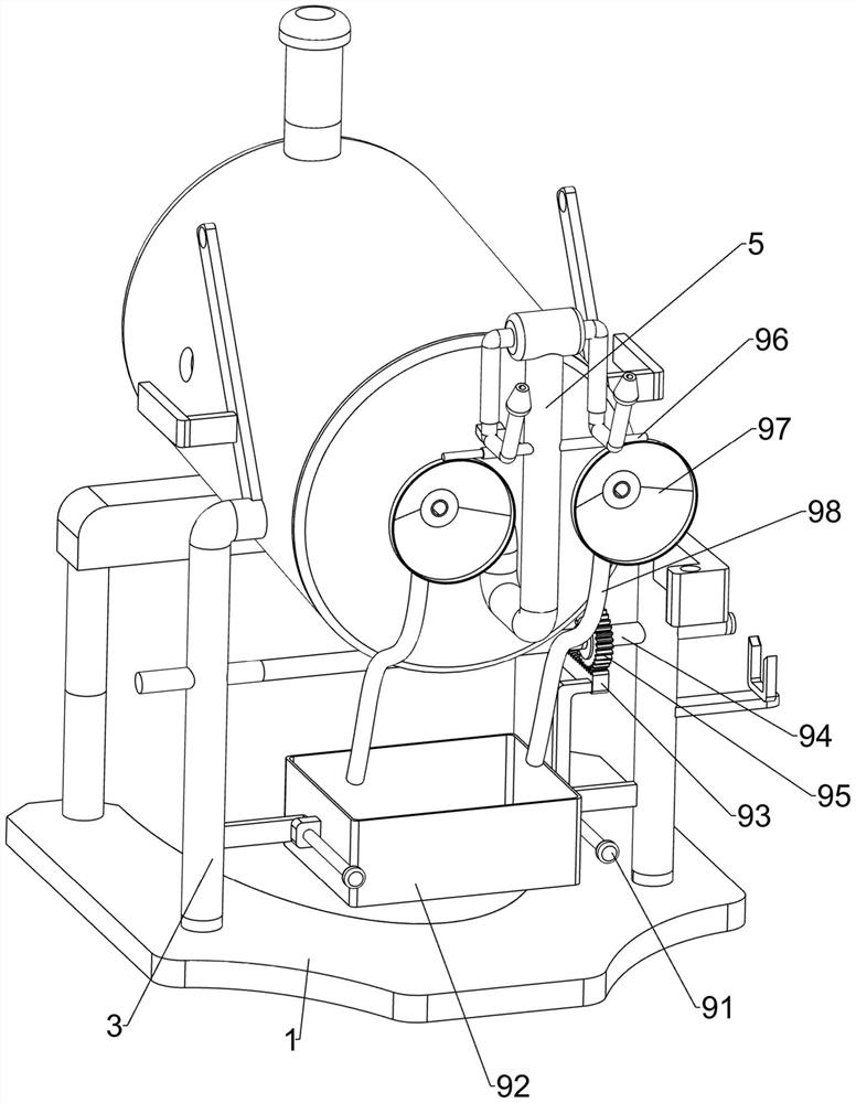
[0031] A nasal irrigation device such as Figure 1-3 As shown, it includes a base 1, a box body 2, legs 3, a water storage tank 4, an outlet pipe 5, a connecting pipe 6, a flushing head 7, an extruding assembly 8 and a water receiving assembly 9, and the upper part of the base 1 is connected with a box body 2, the top of the base 1 is connected with outriggers 3, the water storage tank 4 is connected between the outriggers 3 on both sides, the front side of the water storage tank 4 is connected with a water outlet pipe 5, and both sides of the top of the water outlet pipe 5 are connected with Connecting pipe 6, the front end of connecting pipe 6 is slidably connected with flushing head 7, extruding assembly 8 is connected on front leg 3, and water receiving assembly 9 is connected at the bottom of front leg 3.
[0032] Extrusion assembly 8 comprises support plate 81, first guide rod 82, extrusion plate 83, vacuum ball 84 and first spring 85, and the upper end of front side sup...
Embodiment 2
[0036] On the basis of Example 1, such as Figure 4As shown, a drive mechanism 10 is also included, and the drive mechanism 10 includes a motor 101, a first pulley 102, a second shaft 103, a second pulley 104, a flat belt 105, a one-way sector gear 106 and a second rack 107, The front leg 3 is connected with a motor 101, the output end of the motor 101 is connected with the first shaft 94, the left and right ends of the first shaft 94 are connected with the first pulley 102, and the top of the front leg 3 is rotatably connected There is a second shaft 103, the right end of the second shaft 103 is connected with a second pulley 104, a flat belt 105 is connected between the second pulley 104 and the first pulley 102, and the left end of the second shaft 103 is connected with a one-way sector The gear 106 is connected with a second rack 107 at the front of the top of the extruding plate 83 , and the second rack 107 is meshed with the one-way sector gear 106 .
[0037] Start the ...
Embodiment 3
[0039] On the basis of Example 2, such as Figure 5-7 As shown, it also includes a punch changing assembly 11, and the punch changing assembly 11 includes a circular fixed plate 111, a push plate 112, a U-shaped connecting rod 113, a gear lever 114 and a second spring 115, and the front part of the connecting pipe 6 Connected with a circular fixed plate 111, the front end of the connecting pipe 6 is slidably connected with a push plate 112, the bottom of the push plate 112 is connected with a U-shaped connecting rod 113, and the middle part of the connecting pipe 6 is slidably connected with a gear lever 114. The rod 114 cooperates with the U-shaped connecting rod 113 , and a second spring 115 is connected between the circular fixing plate 111 and the push plate 112 , and the second spring 115 is sheathed on the U-shaped connecting rod 113 .
[0040] At first, the second spring 115 is in a compressed state, moving the gear rod 114 backward, the U-shaped connecting rod 113 move...
PUM
 Abstract
Description
Claims
Application Information
 - R&D
- Intellectual Property
- Life Sciences
- Materials
- Tech Scout
- Unparalleled Data Quality
- Higher Quality Content
- 60% Fewer Hallucinations
Browse by: Latest US Patents, China's latest patents, Technical Efficacy Thesaurus, Application Domain, Technology Topic, Popular Technical Reports.
© 2025 PatSnap. All rights reserved.Legal|Privacy policy|Modern Slavery Act Transparency Statement|Sitemap|About US| Contact US: help@patsnap.com


