Parallel ankle joint rehabilitation system flexibly driven by pneumatic muscles and control method thereof

A pneumatic muscle and ankle joint technology, which is applied in the directions of muscle training equipment, sports accessories, passive exercise equipment, etc., can solve the problems of difficulty in realizing the patient's rehabilitation training needs, poor flexibility and safety, and a single rehabilitation training mode, and achieve convenient The effect of layout and replacement, low cost and stable system performance

Active Publication Date: 2021-09-03
XI AN JIAOTONG UNIV
View PDF9 Cites 1 Cited by
  • Summary
  • Abstract
  • Description
  • Claims
  • Application Information

AI Technical Summary

Problems solved by technology

However, most of the existing medical rehabilitation equipment directly uses rigid motors as the driving source, which makes the overall flexibility and safety of the mechanism relatively poor. new injuries, so it is necessary to design a compliant and safe rehabilitation mechanism
[0003] In addition, the current control of the training mode of ankle joint rehabilitation institutions mainly focuses on setting the corresponding movement trajectory of the mechanism in advance and tracking the trajectory of the terminal mechanism to achieve early rehabilitation training. Rehabilitation Training Requirements in the Rehabilitation Phase

Method used


Image

  • Parallel ankle joint rehabilitation system flexibly driven by pneumatic muscles and control method thereof
  • Parallel ankle joint rehabilitation system flexibly driven by pneumatic muscles and control method thereof
  • Parallel ankle joint rehabilitation system flexibly driven by pneumatic muscles and control method thereof

Examples


Embodiment Construction

[0037] The present invention will be described in further detail below in conjunction with the accompanying drawings.

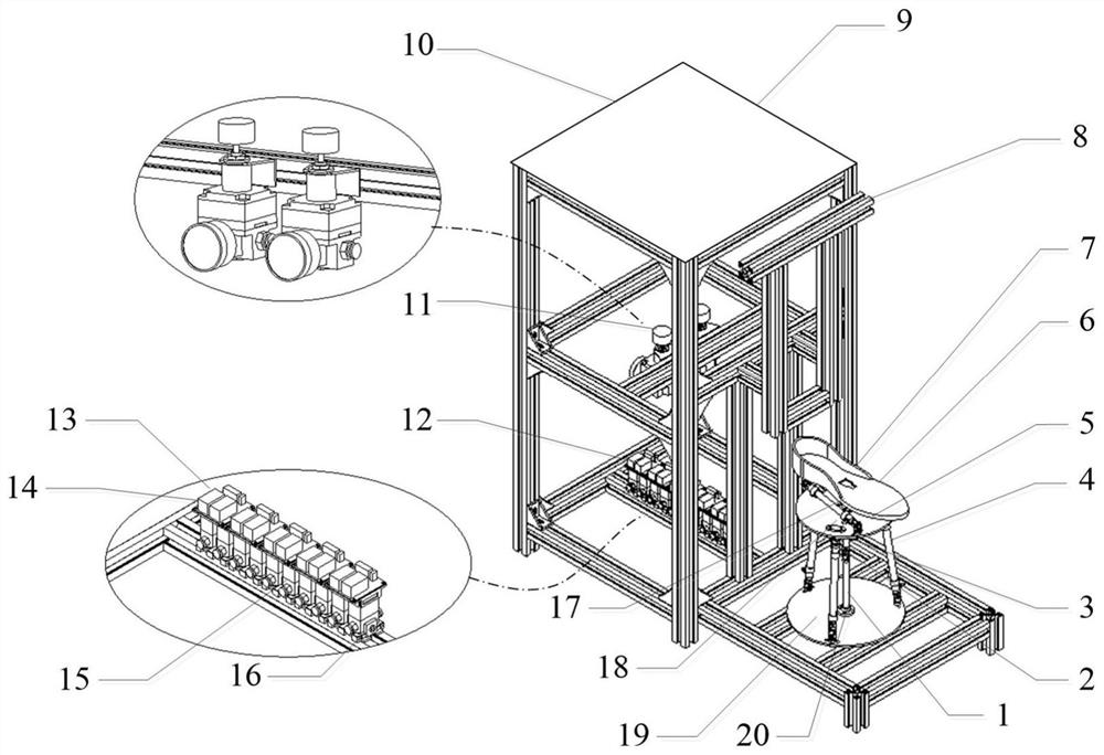
[0038] see figure 1According to the present invention, a parallel ankle joint rehabilitation system driven by pneumatic muscles is flexible, and the parallel ankle joint rehabilitation system includes a parallel ankle joint rehabilitation mechanism 7 connected together by bolts and nuts, a control seat 9 and a main control system; Wherein, the parallel ankle joint rehabilitation mechanism 7 includes an upper platform 5, a lower platform 19, a foot support module 6, a pneumatic muscle 4, a foot support support rod 17, an upper support rod 3, a lower support rod 1, a flange 20, a Lanpan 18 and Hooke hinge 2; said lower platform 19 is fixedly installed on the frame of the front part of the control seat 9, and the lower support rod 1 is fixedly connected to the center of the lower platform 19 through the flange 20, and the upper support rod 3 The center of the u...


PUM


Abstract

The invention discloses a parallel ankle joint rehabilitation system flexibly driven by pneumatic muscles and a control method thereof. The parallel ankle joint rehabilitation system comprises a parallel ankle joint rehabilitation mechanism and a control seat, wherein the rehabilitation mechanism comprises an upper/lower platform, a foot support module, the pneumatic muscles, a foot support supporting rod, an upper/lower supporting rod, a flange, a flange plate and a Hook hinge, and the control seat comprises an adjustable foot stool, a pressure reducing valve set, an integrated valve block set and a seat rack. The rehabilitation training control method comprises the steps of selecting a training mode, setting related parameters, determining an expected movement track, solving the expected length of each pneumatic muscle, and carrying out air pressure control and length closed-loop control on each pneumatic muscle, thereby realizing the overall control of the rehabilitation mechanism. According to the rehabilitation system disclosed by the invention, a set of soft and safe rehabilitation equipment and rehabilitation training methods under different requirements are provided for people suffering from ankle joint injury, the rehabilitation effect of patients is improved, and the initiative and enthusiasm of the patients in a rehabilitation training process are improved.

Description

technical field [0001] The invention belongs to the technical field of medical rehabilitation equipment, in particular to a parallel ankle joint rehabilitation system and control method driven by pneumatic muscles flexibly. Background technique [0002] For patients with ankle joint injuries, the treatment method is generally one-on-one staged training by the doctor, so as to gradually restore the motor function of the patient's ankle joint, but the final effect of this treatment method often depends on the doctor's clinical experience and The subjective judgment of the patient's recovery situation also leads to relatively low treatment efficiency. With the widespread application of robotics, medical rehabilitation robots have been widely used in high-precision minimally invasive surgery, rehabilitation training, and medical assistance, making a new breakthrough in the treatment of ankle joint injuries. However, most of the existing medical rehabilitation equipment directly...

Claims


Application Information

Patent Timeline
Patent Type & Authority Applications(China)
IPC IPC(8): A63B23/08A63B21/00A63B24/00A61H1/02
CPCA63B23/08A63B21/00178A63B24/0087A61H1/0266A61H2201/0149A61H2201/1238A61H2201/1642A61H2201/5056A61H2201/5071A61H2205/12
Inventor 王孙安刘文捷周民张斌权于镇源
Owner XI AN JIAOTONG UNIV
Why Eureka
Try Eureka