A stamping device for machining inner and outer rings of bearings
A technology of stamping device and inner and outer rings, applied in the field of bearing processing, can solve the problems of low safety factor of manual reclaiming, inability to collect waste, complicated stamping steps, etc., and achieve the effects of convenient subsequent collection, convenient operation and reasonable structure design.
- Summary
- Abstract
- Description
- Claims
- Application Information
AI Technical Summary
Problems solved by technology
Method used
Image
Examples
Embodiment 1
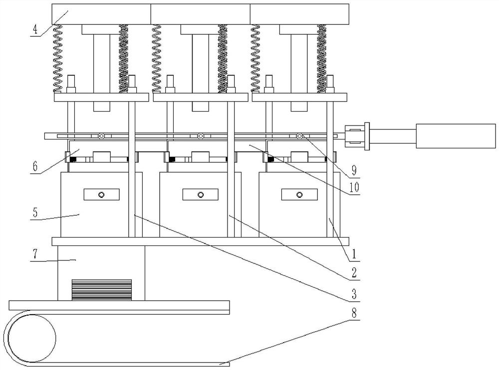
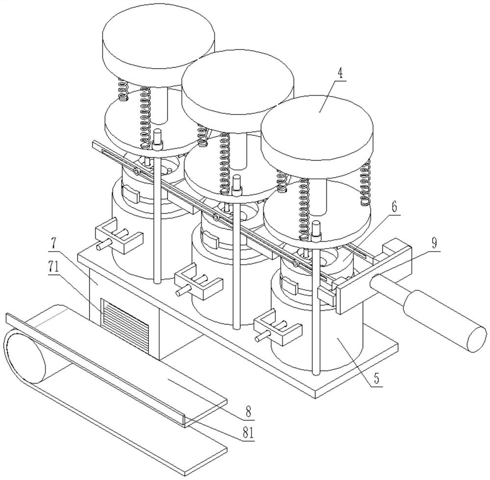
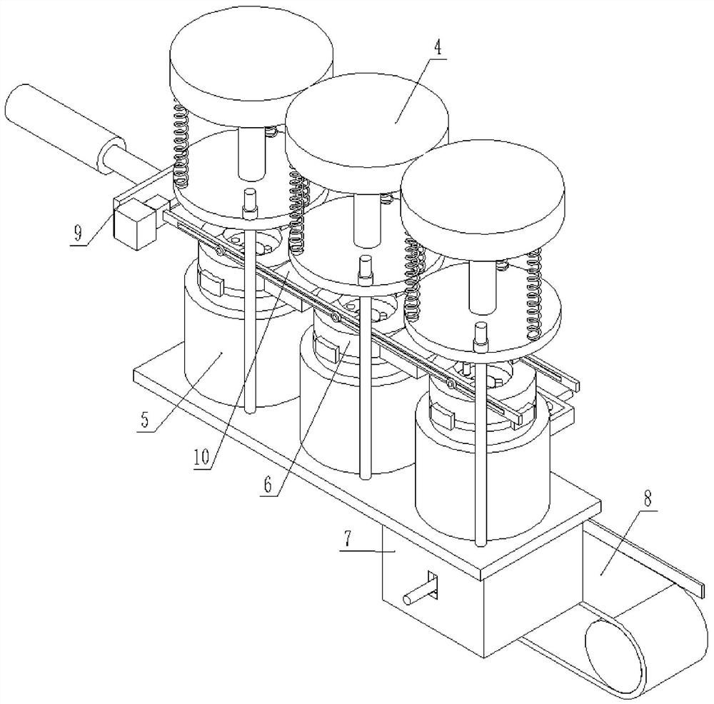
[0042] A stamping device for processing inner and outer rings of bearings, such as Figure 1-Figure 4 As shown, it includes pier roughing station 1, punching station 2 and punching station 3 stations which are arranged in sequence. The stations are respectively provided with a stamping mechanism 4 and a height-adjustable stamping seat 5. Between the stations are The transition plate 10, the top surface of the transition plate 10 is flush with the bottom surface of the material on the station. When the material is moved along different stations, the transition plate 10 plays a supporting role to prevent the material from falling between the stations due to accidents and ensure smooth processing.
[0043] Described stamping mechanism 4 comprises the stamping head that has power source, and the upper mold that adapts to lower mold 6 is installed on one side of stamping head, is provided with damping spring between described power source and upper mold, and upper mold and A guide...
Embodiment 2
[0054] On the basis of Example 1, such as Figure 4 As shown, an opening 71 is provided on one side of the waste collection box 7, and an inclined guide plate 72 is movably installed in the lower part of the collection box, and one end of the guide plate 72 presses against the inner wall of the box. The opening 71 and the guide plate 72 correspond to the conveying line 8 . The guide plate 72 can play a buffering role to prevent unnecessary damage to the conveying line 8 caused by waste materials falling directly onto the conveying line 8 .
[0055] One side of the waste collection box 7 is provided with an adjusting rod 73 for moving the guide plate 72, and one side of the waste collection box 7 is provided with a through hole, and a connecting shaft is arranged in the through hole, and the adjusting rod 73 is set on the connecting shaft. ; The adjusting rod 73 is provided with a long slot matched with the connecting shaft, so that the position of the adjusting rod 73 in the ...
Embodiment 3
[0060] On the basis of Example 1 and Example 2, as Figure 7 and Figure 8 As shown, a relatively movable clamp assembly 9 is provided on one side of the station, and the clamp assembly 9 moves along the direction of the roughing station 1, the punching station 2 and the punching station 3. That is to clamp the processed materials at different stations and move to the next station. After reaching the next station, the clamp assembly 9 releases the materials, so that the materials fall to the next station and are processed accordingly. At this time, the clamp Component 9 resets to move the material next time.
[0061] The clamp assembly 9 includes a mounting rod 91 with a clamp 93, a screw nut mechanism 95, a cylinder 96 and a riser 97, and one end of the mounting rod 91 is provided with a screw nut mechanism 95 that makes it move relatively. The cooperation of the lead screw nut drives the installation rod 91 to move, and then the clamp 93 clamps or loosens the material. A ...
PUM
 Abstract
Description
Claims
Application Information
 - R&D
- Intellectual Property
- Life Sciences
- Materials
- Tech Scout
- Unparalleled Data Quality
- Higher Quality Content
- 60% Fewer Hallucinations
Browse by: Latest US Patents, China's latest patents, Technical Efficacy Thesaurus, Application Domain, Technology Topic, Popular Technical Reports.
© 2025 PatSnap. All rights reserved.Legal|Privacy policy|Modern Slavery Act Transparency Statement|Sitemap|About US| Contact US: help@patsnap.com


