Forming positioning device for copper strip manufacturing

A technology for positioning devices and copper strips, applied in the direction of shearing devices, spraying devices, manufacturing tools, etc., can solve the problems of unfavorable processing operations of copper strips, affecting manufacturing efficiency, etc., to avoid ink precipitation, improve spraying effect, and stability high effect

Active Publication Date: 2021-09-03
江苏兴成新材料有限公司
View PDF9 Cites 0 Cited by
  • Summary
  • Abstract
  • Description
  • Claims
  • Application Information

AI Technical Summary

Problems solved by technology

[0004] Existing patent No. CN103920824B proposes forming positioning device, comprises patrix, locating ring, cushion, template, pressing plate and punch, and described template is positioned at the bottom of whole device, and described punch is arranged on the top of template, and described punch Set coaxially with the template, the punch is a cylinder with a fixed expansion platform at the lower end, a groove in the middle, and a working size cylinder at the upper end. The pressing plate is arranged on the outer ring of the fixed expansion platform of the punch, and The inner side is provided with a card slot, and the card slot is correspondingly clamped on the fixed expansion platform of the punch, the pressure plate is fixed on the template by bolts, and a positioning ring is arranged on the groove in the middle of the punch. The ring is composed of three positioning flaps and a positioning hole which is close

Method used


Image

  • Forming positioning device for copper strip manufacturing
  • Forming positioning device for copper strip manufacturing
  • Forming positioning device for copper strip manufacturing

Examples


Embodiment Construction

[0034] The following will clearly and completely describe the technical solutions in the embodiments of the present invention with reference to the accompanying drawings in the embodiments of the present invention. Obviously, the described embodiments are only some, not all, embodiments of the present invention. Based on the embodiments of the present invention, all other embodiments obtained by persons of ordinary skill in the art without making creative efforts belong to the protection scope of the present invention.

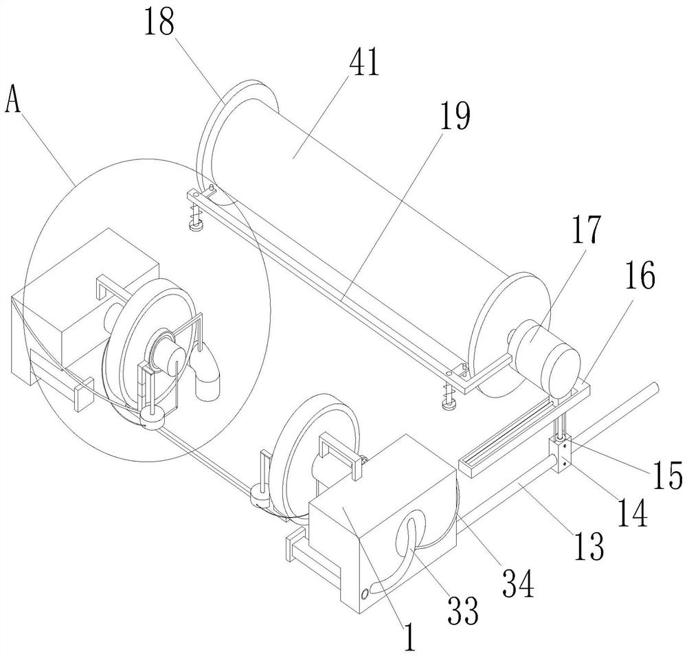
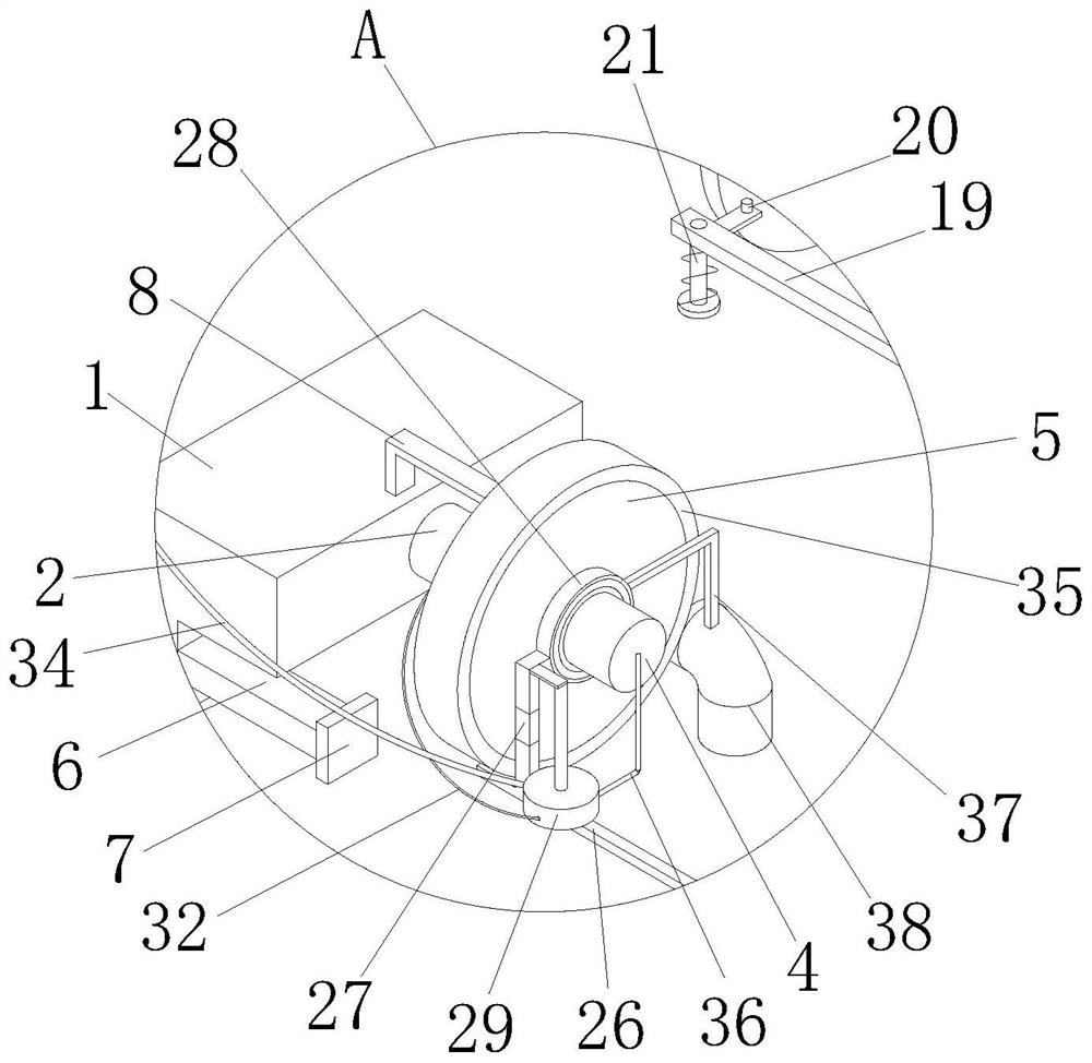
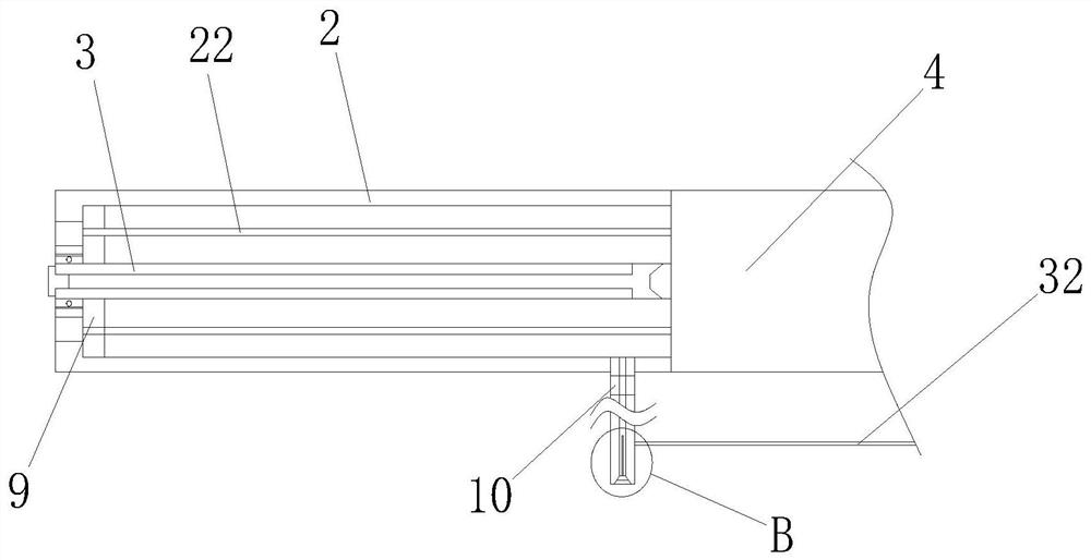
[0035] see Figure 1-8 , a forming and positioning device for copper strip manufacturing, comprising an inverted L-shaped fixed block 1, the number of fixed blocks 1 is two and corresponding to the left and right, the upper end of the side of the fixed block 1 is provided with a hole and is fixedly connected with a sleeve 2, The center of the side of the sleeve 2 is provided with a hole and is connected with a connecting shaft 3 through a rotating bearing. The...


PUM


Abstract

The invention relates to the technical field of copper strip manufacturing, and discloses a forming positioning device for copper strip manufacturing. The forming positioning device for copper strip manufacturing comprises two inverted-L-shaped fixing blocks, the two fixing blocks correspond to each other left and right, air cushions are fixedly connected to the bottom ends of the corresponding faces of the two fixing blocks, and touch plates are fixedly connected to the corresponding ends of the two air cushions. Through the arrangement of the touch plates, a spraying rod is triggered in a pneumatic mode to mark the protruding position of a copper strip, compared with an existing sensor detection mode, the beneficial effects of being rapid in response and high in stability are achieved, the device is suitable for being used for a long time, the two touch plates can change the distance according to the shape of the copper strip, and conveying of the copper strip is prevented from being hindered; and ink is sprayed only when the spraying rod corresponds to the protruding position of the copper strip, the ink is stored in a closed space in a sleeve at ordinary times, and therefore the problems that in existing spraying, the spraying effect is poor after drying, and cleaning is difficult due to dirt and ink dripping caused by continuous attaching of the copper strip are solved.

Description

technical field [0001] The invention relates to the technical field of copper strip manufacture, in particular to a forming and positioning device for copper strip manufacture. Background technique [0002] Copper strip is a kind of metal component. The product specification is 0.1~3×50~250mm copper strip products in various states. It is mainly used for the production of electrical components, lamp holders, battery caps, buttons, seals and connectors. It is mainly used for conductive , heat conduction, and corrosion-resistant equipment, in the manufacturing process of the copper strip, it is necessary to use a forming positioning device to fix the position of the copper strip and trim and shape it. [0003] The existing patent No. CN203644470U proposes a positioning device for copper strip forming, which includes a positioning component, a left and right adjustment component, a bracket component and a guide component. The positioning components are symmetrically installed o...

Claims


Application Information

Patent Timeline
IPC IPC(8): B23P23/04B23D19/00B23D33/02B23D33/00B23Q17/24B24B7/06B05B13/02B05B15/25B05B16/20
CPCB23P23/04B23D19/00B23D33/02B23D33/00B23Q17/24B24B7/06B05B13/0221B05B15/25B05B16/20
Inventor 王明龙
Owner 江苏兴成新材料有限公司
Why Eureka
Try Eureka