
Vacuum tube

A vacuum tube and vacuum heat insulation technology, which is applied in the field of vacuum tubes, can solve the problems of increased diameter, increased material and production costs, and bulkiness of vacuum tubes, and achieve the effects of shortening length, reducing production costs, and reducing body shape

Pending Publication Date: 2021-09-03
SHANGHAI XINGYE MATERIALS TECH CO LTD
View PDF1 Cites 1 Cited by
  • Summary
  • Abstract
  • Description
  • Claims
  • Application Information

AI Technical Summary

Problems solved by technology

The protruding ring increases the maximum outer diameter of the inner tube. In order to ensure the aforementioned gap, the diameter of the outer tube must be increased, resulting in an increase in the overall diameter of the vacuum tube, which is not only bulky, but also increases the cost of materials and production.

Method used


Image

  • Vacuum tube
  • Vacuum tube
  • Vacuum tube

Examples


Embodiment 1

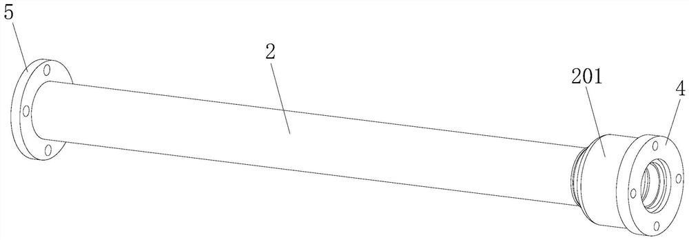
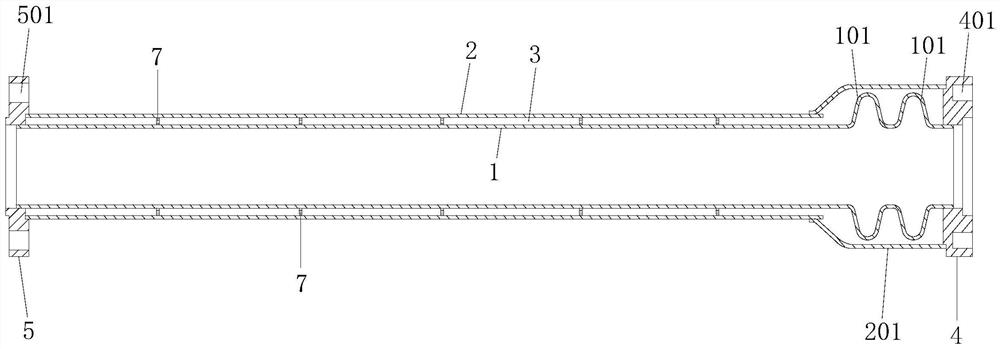
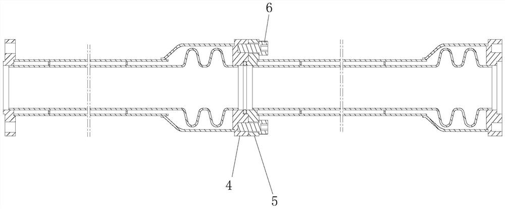
[0057] Figure 1 to Figure 4 A first embodiment of the vacuum tube of the present application is shown, which has a first end and a second end oppositely arranged in its length direction, wherein the first end is figure 2 The right end of the medium vacuum tube, the second end is figure 2 The left end of the medium vacuum tube. The vacuum tube includes an inner tube 1, an outer tube 2, and a vacuum insulation chamber 3 formed between the inner tube and the outer tube. The inner tube 1 has a third end at the aforementioned first end and a fourth end at the aforementioned second end. The outer tube 2 is arranged on the periphery of the inner tube 1, and has a fifth end located at the aforementioned first end and a sixth end located at the aforementioned second end. In this embodiment, the aforementioned third end of the inner tube 1 is figure 2 The right end of the middle inner tube, the aforementioned fourth end of the inner tube 1 is also figure 2 The left end of the ...

Embodiment 2

[0077] Figure 6 The second embodiment of the vacuum tube of the present application is shown, which has basically the same structure as that of the first embodiment, the only difference being that the second embodiment only has one first ring 102 .

Embodiment 3

[0079] Figure 7 to Figure 10 The third embodiment of the vacuum tube of the present application is shown, which also has basically the same structure as that of the first embodiment, the main difference being that the third embodiment of the third embodiment is provided with two first rings at the third end of the inner tube 1 In addition to 101, two second rings 102 are provided at the other end of the inner tube 1, that is, the fourth end.

[0080] The second ring 102 has the same structure as the first ring 101 , and is also a radially outwardly convex structure integrally formed on the tube wall of the inner tube 1 and surrounding the periphery of the axis of the inner tube 1 .

[0081] When the length of the vacuum tube is relatively large, it will be difficult to fully absorb / compensate the telescopic deformation of the inner tube if only one or two rings are provided on the inner tube 2 . Therefore, in this embodiment, four rings—two first rings 101 and two second rin...


PUM


Abstract

The application relates to a vacuum tube. The vacuum tube is provided with a first end and a second end arranged opposite to each other in the length direction. The vacuum tube comprises an inner tube having a third end at the first end and a fourth end at the second end, an outer tube which is arranged on the periphery of the inner tube and provided with a fifth end located at the first end and a sixth end located at the second end, a vacuum heat insulation cavity which is formed between the inner tube and the outer tube, and one or more first folding ring, wherein each of the first folding rings is of a radial convex structure which is integrally formed on the tube wall of the inner tube and surrounds the periphery of the axis of the inner tube, and each of the first folding rings is arranged at the third end. According to the vacuum tube, the outer tube diameter of the vacuum tube can be reduced under the condition that the through-flow capacity of the vacuum tube is not reduced.

Description

technical field [0001] This application relates to a vacuum tube. Background technique [0002] For the inner and outer tubes, especially the vacuum tubes composed of inner and outer tubes, when the temperature of the transported fluid changes, the temperature of the inner tube that is in direct contact with the fluid changes rapidly, and the inner tube will be generated due to the temperature change. The expansion and contraction deformation in the length direction, the outer tube around the inner tube will not produce obvious temperature changes because it is minimally affected by the temperature of the fluid in the tube, and then there will be no obvious expansion and contraction deformation, which will easily cause the vacuum tube to bend and deform, or even leak. loses its ability to insulate. [0003] For the above problems, the Chinese invention application with publication number 112377725A proposes to set an axially deformable outwardly convex collar on the inner t...

Claims


Application Information

Patent Timeline
Patent Type & Authority Applications(China)
IPC IPC(8): F16L51/02F16L59/065F16L23/024
CPCF16L51/023F16L59/065F16L23/024
Inventor 高峰刘在祥陈艳凤蔡园丰王兵牛争艳
Owner SHANGHAI XINGYE MATERIALS TECH CO LTD
Learn More