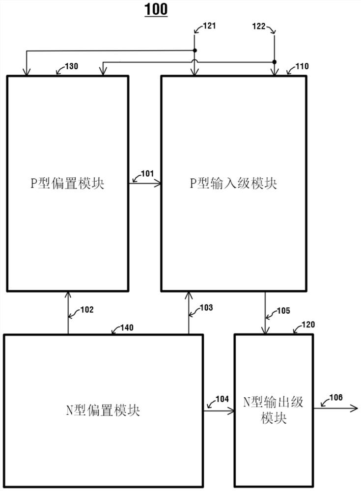
Differential voltage detection circuit with wide voltage input range
A wide voltage input and differential voltage technology, applied in the field of integrated circuits, can solve the problems of small input offset voltage and narrow voltage input range, and achieve the effect of reducing input offset voltage and strong practicability
- Summary
- Abstract
- Description
- Claims
- Application Information
AI Technical Summary
Problems solved by technology
Method used
Image
Examples
Embodiment 1
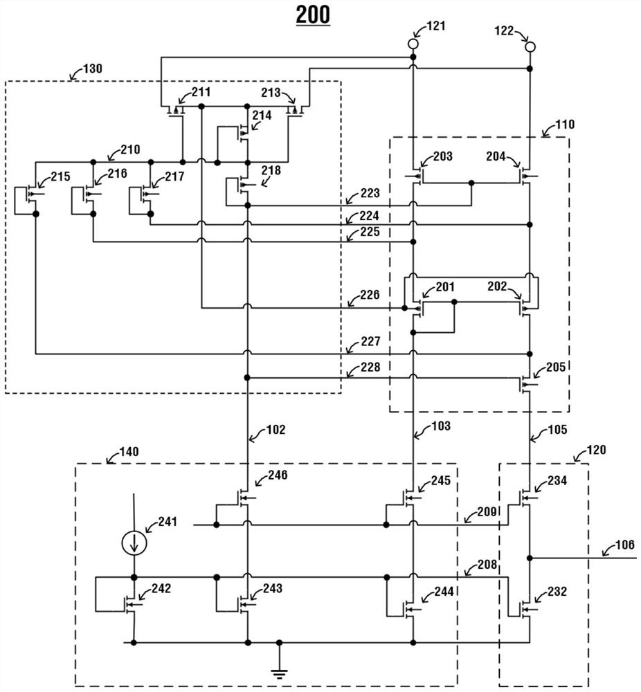
[0075] figure 2 It is a schematic diagram of a specific implementation circuit 200 of a differential voltage detection circuit with a wide voltage input range in this embodiment, wherein,
[0076] The P-type input stage module 110 includes a first PMOS transistor 201 , a second PMOS transistor 202 , a third PMOS transistor 203 , a fourth PMOS transistor 204 and a fifth PMOS transistor 205 . The third PMOS transistor 203 , the fourth PMOS transistor 204 and the fifth PMOS transistor 205 are high-voltage PMOS transistors, and the drain-source of the high-voltage PMOS transistors can withstand tens of volts or even hundreds of volts.
[0077] Wherein, the first PMOS transistor 201 and the second PMOS transistor 202 form a differential pair, and the gate of the first PMOS transistor 201 is connected to the gate of the second PMOS transistor 202 . The first PMOS transistor 201 and the second PMOS transistor 202 share the same N well on the chip layout, that is, they share a back ...
Embodiment 2
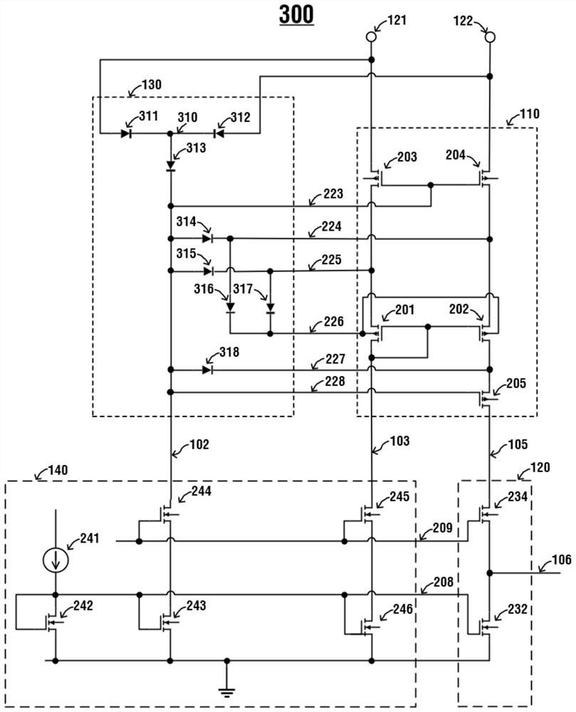
[0116] image 3 It is a schematic diagram of a specific implementation circuit of a differential voltage detection circuit with a wide voltage input range in Embodiment 2 of the present application. The specific implementation circuit 300 of a differential voltage detection circuit with a wide voltage input range differs from Embodiment 1 only in that P type bias module 130 . The function of the P-type bias module 130 is still to provide bias and clamp functions to the transistors inside the P-type input stage 110 .
[0117] The P-type bias module 130 includes a first diode 311, a second diode 312, a third diode 313, a fourth diode 314, a fifth diode 315, a sixth diode 316, a The seven diodes 317 and the eighth diode 318, wherein the first diode 311 and the second diode 312 are high voltage diodes.
[0118] The anode of the first diode 311 is connected to the first voltage input signal 121, the anode of the second diode 312 is connected to the second voltage input signal 122...
Embodiment 3
[0125] Figure 4 It is a schematic diagram of a specific implementation circuit of a differential voltage detection circuit with a wide voltage input range in Embodiment 3 of the present application. The specific implementation circuit 400 of a differential voltage detection circuit with a wide voltage input range is implemented on the basis of Embodiment 3. The optimization, its difference with embodiment three only lies in: image 3 The sixth diode 316 and the seventh diode 317 in the P-type bias module 130 are in Figure 4 is replaced by a thirteenth PMOS transistor 416 and a fourteenth PMOS transistor 417 .
[0126] The drain of the thirteenth PMOS transistor 416 is connected to the cathode of the fourth diode 314 (ie, the connection line 224), and the gate of the thirteenth PMOS transistor 416 is connected to the cathode of the fifth diode 315 (ie, the connection line 225). The sources of the thirteenth PMOS transistor 416 and the fourteenth PMOS transistor 417 are both...
PUM
 Abstract
Description
Claims
Application Information
 - R&D
- Intellectual Property
- Life Sciences
- Materials
- Tech Scout
- Unparalleled Data Quality
- Higher Quality Content
- 60% Fewer Hallucinations
Browse by: Latest US Patents, China's latest patents, Technical Efficacy Thesaurus, Application Domain, Technology Topic, Popular Technical Reports.
© 2025 PatSnap. All rights reserved.Legal|Privacy policy|Modern Slavery Act Transparency Statement|Sitemap|About US| Contact US: help@patsnap.com


