
Insertion core, optical fiber connector and manufacturing method of insertion core

A ferrule and optical fiber technology, applied in the field of optical communication, can solve problems such as high insertion force, high cost of optical fiber connectors, pollution, etc., and achieve the effects of prolonging service life, low precision requirements, and reducing manufacturing costs

Active Publication Date: 2021-09-03
HUAWEI TECH CO LTD
View PDF7 Cites 0 Cited by
  • Summary
  • Abstract
  • Description
  • Claims
  • Application Information

AI Technical Summary

Problems solved by technology

The existing NC optical fiber connectors cannot realize the non-physical contact of the optical fibers of the two optical fiber connectors when they are docked with all kinds of optical fiber connectors including ferrules, so that the insertion and extraction force of the two optical fiber connectors is high when they are docked. , when plugging and unplugging many times, the connection end face will be worn and polluted; and the optical fiber in the other optical fiber connector that is docked with the existing NC optical fiber connector is easy to touch the ferrule body of the NC optical fiber connector when docking , resulting in wear and tear of the optical fiber, so the reliability of plugging and unplugging is not high. To improve the reliability of plugging and unplugging, it is necessary to manufacture NC fiber optic connectors with high precision, and the cost of fiber optic connectors is relatively high.

Method used


Image

  • Insertion core, optical fiber connector and manufacturing method of insertion core
  • Insertion core, optical fiber connector and manufacturing method of insertion core
  • Insertion core, optical fiber connector and manufacturing method of insertion core

Examples


Embodiment 1

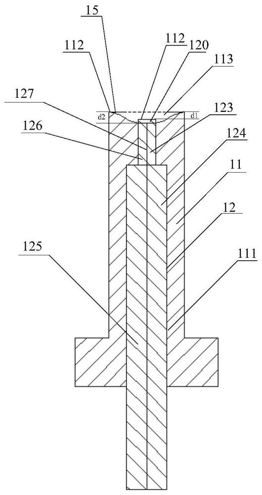
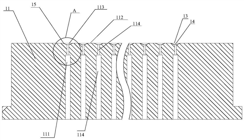
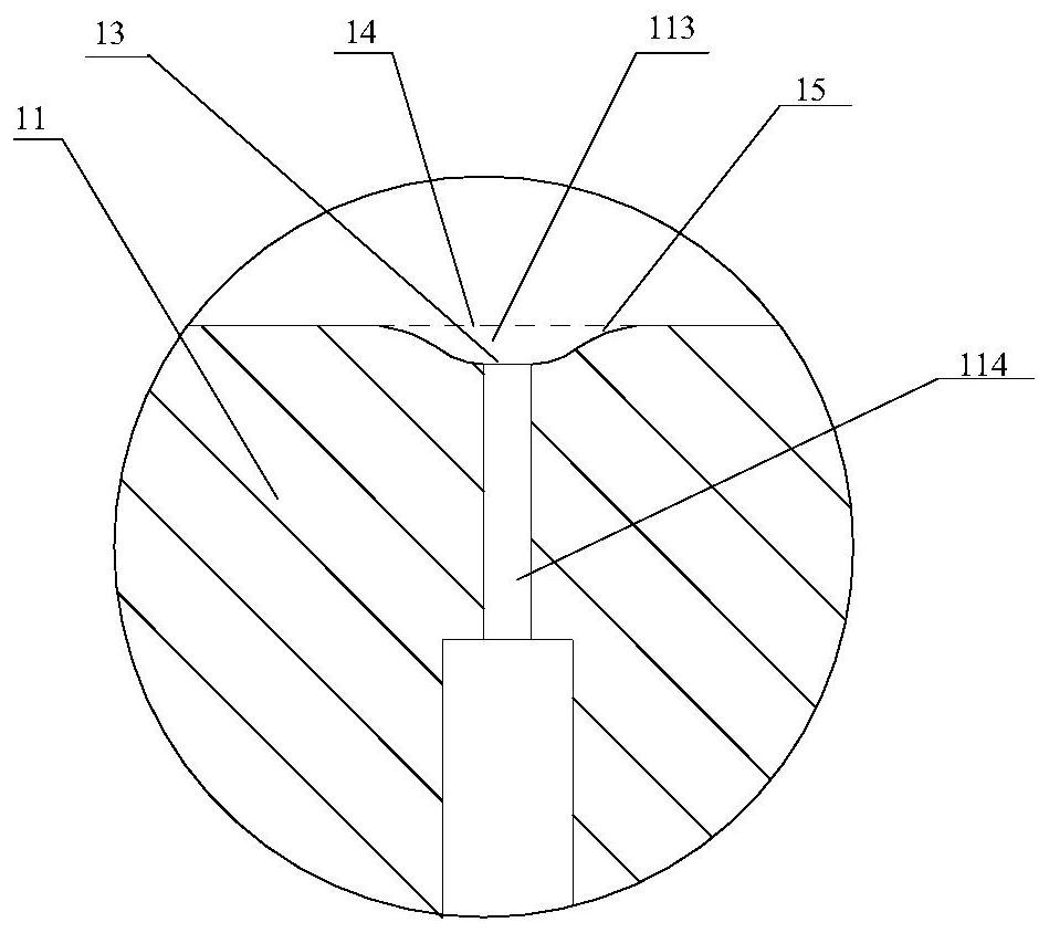
[0158] figure 1 Partial cross-sectional cross section of the ferrule provided by the embodiment of the present application Figure one , figure 2 The cross-sectional schematic of the ferrule body provided by the embodiment of the present application Figure one , image 3 for figure 2 Part A part of the partial enlargement map, Figure 4 Partial cross-sectional cross section of the ferrule provided by the embodiment of the present application Figure II , Figure 5 The cross-sectional schematic of the ferrule body provided by the embodiment of the present application Figure II , Image 6 As a part of the Part B in Fig. 5.

[0159] See Figure 1 to 6 In the present application, in the present application, the internal axial direction of the ferrule body 11 is provided with at least one through hole 111, and for each optical fiber, the optical fiber 12 is formed in the respective through hole 111, and the first end 120 of the optical fiber 12 is located in pass. The vertical distance betwe...

Embodiment 2

[0178] Based on the previous embodiment, the present embodiment describes the setting of the first predetermined distance in the first embodiment.

[0179] The first preset distance in this embodiment is a distance between the optical fibers of the ferrule 100 to the optical fibers of the ferrule 100 and the other ferrule, including the present embodiment. After the optical fiber connector of the ferrule 100 is connected to the fiber optic connector including another ferrule, the optical fiber of the fiber optic connector of the ferrule 100 in the present embodiment has a fiber corresponding to the other ferrule fiber. gap.

[0180] Among them, the first preset distance can be connected to the distance of the end surface according to the current conventional MT-chuck fiber optic connector (also mentioned that the optical fiber protruding body of the conventional MT ferrule is connected to the end surface, below The first preset distance can be greater than the conventional MT stri...

Embodiment 3

[0189] Based on the above embodiment, the present embodiment describes the setting of the first segment through hole 113 of the ferrule 100 in the above embodiments.

[0190] In the present embodiment, the first segment through hole 113 is larger than any cross section of any of the axial directions perpendicular to the core body, and the area of ​​the end face 121 of the optical fiber 12, and the optical fiber 12 is in the axial direction The projection is not overlapped with the first segment through hole 113 overlaps the projection of any cross section perpendicular to the axial direction of the ferrule body 11.

[0191] Specifically, the shape of the first passage 113 may be a regular shape or an irregular shape, as long as the area of ​​any of the first segment through holes 113 is perpendicular to the axial direction in the axial direction of the ferrule body is greater than the optical fiber 12 The area of ​​the end surface 121 of the first end 120 is not overlapped with th...


PUM

PropertyMeasurementUnit
diameteraaaaaaaaaa
refractive indexaaaaaaaaaa

Abstract

The embodiment of the invention provides an insertion core, an optical fiber connector and a preparation method of the insertion core. The insertion core comprises an insertion core body and at least one optical fiber. The optical fiber penetrates through a through hole axially arranged in the insertion core body, a first end of the optical fiber is located in the through hole, the vertical distance between the end face of the first end of the optical fiber and the plane where the connecting end face of the insertion core body is located is a first preset distance, and the first preset distance enables the end face of the first end of the optical fiber to be located after the insertion core is in butt joint with another insertion core, so that a gap distance is formed between the optical fiber of one insertion core and the optical fiber of the other insertion core; the through hole comprises a first-section through hole, the plane where the top of the first-section through hole is located is the plane where the connecting end face of the ferrule body is located, and the intersection of the projection of the optical fiber in the axial direction and the projection of any cross section, perpendicular to the axial direction, of the first-section through hole is the projection of the optical fiber in the axial direction; and an anti-reflection film is plated on the outer wall of the optical fiber in the first section of through hole. According to the insertion core provided by the embodiment of the invention, the transmission loss of light is relatively small, the dust holding capacity is relatively good, and when the insertion core provided by the embodiment of the invention is inserted into and pulled out of another insertion core, the insertion and pulling force is relatively small, and the insertion and pulling reliability is relatively high.

Description

Technical field [0001] The present application embodiment relates to the field of optical communication, and more particularly to a ferrule, a fiber optic connector, and a method of fabricating the ferrule. Background technique [0002] In the optical communication system of the optical fiber as a transmission medium, the connection between the optical fibers of the optical communication element is divided into a permanent connection and active connection, and the permanent connection is welded, and the active connection is connected to the fiber optic connector. [0003] The existing fiber optic connector in the market includes conventional mechanical docking transmission (MT) ferrule optical fiber connector, lens LENS ferrule fiber optic connector and non-contact (Non-Contact, referred to as NC) fiber optic connector Wait. Conventional MT-chuck fiber optic connector optical fiber protrusions 1-3.5 μm, docking mode relies on mechanical physical contact; lens LENS ferrule fiber o...

Claims


Application Information

Patent Timeline
Patent Type & Authority Applications(China)
IPC IPC(8): G02B6/38G03F7/00G02B1/115G02B1/111C23C14/34C23C14/24C23C14/12C23C14/10C23C14/08
CPCG02B6/3807G02B1/111G02B1/115G03F7/0002C23C14/34C23C14/24C23C14/12C23C14/083C23C14/081C23C14/10G02B6/3847G02B6/403G02B6/3882G02B6/3818G02B6/3885G02B6/3845
Inventor 郭丹王保启
Owner HUAWEI TECH CO LTD
Learn More