
Control method and system for eliminating frequency coupling effect of phase-locked loop of grid-connected device

A technology of coupling effect and control method, applied in the field of power electronics, can solve problems such as failure shutdown, limitation of dynamic response capability of phase-locked loop, transient performance of grid-connected device does not meet the index assessment, etc., to solve the problem of voltage and current distortion at the grid-connected point , Eliminate frequency coupling effect, improve the effect of stable operation ability

Pending Publication Date: 2021-09-03
SHENZHEN HOPEWIND ELECTRIC CO LTD
View PDF0 Cites 0 Cited by
  • Summary
  • Abstract
  • Description
  • Claims
  • Application Information

AI Technical Summary

Problems solved by technology

[0005] To eliminate the interference of the harmonics in the input signal of the phase-locked loop to its output angle, the simplest and direct way is to reduce the bandwidth of the phase-locked loop; The transient performance of grid devices in fault ride-through occasions such as grid voltage drops and grid voltage rises does not meet the index assessment requirements, and in severe cases, it may even lead to fault shutdown
Another approach is to filter the input voltage of the phase-locked loop, and suppress the voltage signal disturbance from entering the phase-locked loop from the source, thereby reducing or even eliminating the possibility of frequency coupling disturbance introduced by phase-locking; in this way, although the phase-locked loop The internal dynamic response capability can be made very fast, but the dynamic response capability of the entire power grid voltage synchronization link will be affected by the filtering of the input voltage signal of the phase-locked loop

Method used


Image

  • Control method and system for eliminating frequency coupling effect of phase-locked loop of grid-connected device
  • Control method and system for eliminating frequency coupling effect of phase-locked loop of grid-connected device
  • Control method and system for eliminating frequency coupling effect of phase-locked loop of grid-connected device

Examples


Embodiment 1

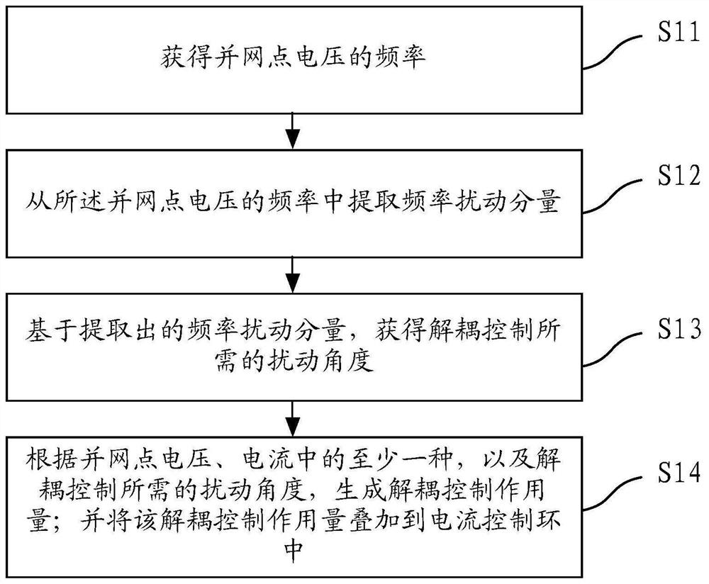
[0042] Such as figure 2 As shown, the embodiment of the present application provides a control method for eliminating the frequency coupling effect of the phase-locked loop of the grid-connected device, and the method includes:

[0043] Step S11, obtaining the frequency of the grid-connected point voltage;

[0044] In this embodiment, the angular frequency ω of the phase-locked loop output can be taken as pll Frequency ω as grid-connected point voltage pcc ; Preferably, take the frequency adjustment Δω output by the phase-locked loop regulator pll Frequency ω as grid-connected point voltage pcc .

[0045] Or, the angular frequency ω calculated according to the α and β axis components of the phase-locked loop input voltage signal seq Frequency ω as grid-connected point voltage pcc , ω seq The specific calculation formula is:

[0046] In the formula, k(k≥1) and k+1 represent the kth control period and the k+1th control period respectively, and T s It is the execution...

Embodiment 2

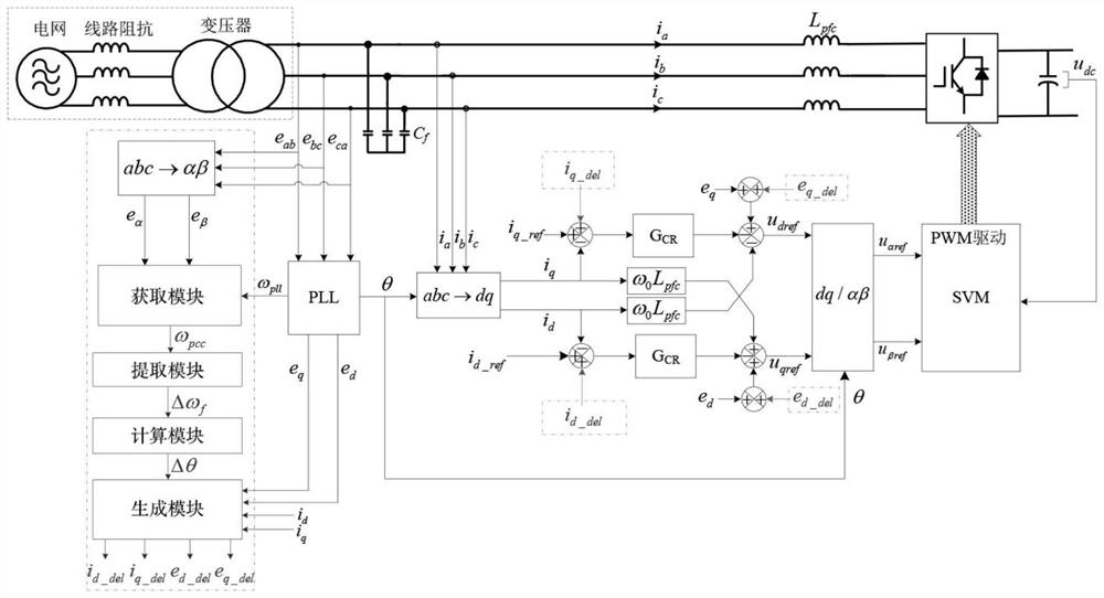
[0060] Such as image 3 As shown, the embodiment of the present application provides a control system for eliminating the frequency coupling effect of the phase-locked loop of the grid-connected device, and the system includes an acquisition module, an extraction module, a calculation module, and a generation module;

[0061] The obtaining module is used to obtain the frequency of the grid-connected point voltage;

[0062] In this embodiment, the angular frequency ω of the phase-locked loop output can be taken as pll Frequency ω as grid-connected point voltage pcc ; Preferably, take the frequency adjustment Δω output by the phase-locked loop regulator pll Frequency ω as grid-connected point voltage pcc .

[0063] Or, the angular frequency ω calculated according to the α and β axis components of the phase-locked loop input voltage signal seq Frequency ω as grid-connected point voltage pcc , ω seq The specific calculation formula is:

[0064] In the formula, k(k≥1) and...

Embodiment 3

[0078] Such as Figure 5 As shown, the embodiment of the present application provides a control system for eliminating the frequency coupling effect of the phase-locked loop of the grid-connected device. The system includes a memory 21, a processor 22 and a The control program for eliminating the frequency coupling effect of the phase-locked loop of the grid-connected device running on the network, when the control program for eliminating the frequency coupling effect of the phase-locked loop of the grid-connected device is executed by the processor 22, it is used to achieve the elimination described in Embodiment 1 The steps of the method for controlling the frequency coupling effect of a phase-locked loop of a grid-connected device.


PUM


Abstract

The invention discloses a control method and system for eliminating a frequency coupling effect of a phase-locked loop of a grid-connected device. The method comprises the following steps of: acquiring the frequency of the voltage of a grid-connected point; extracting a frequency disturbance component from the frequency of the grid-connected point voltage; acquiring a disturbance angle required by decoupling control based on the extracted frequency disturbance component; generating a decoupling control action quantity according to at least one of the voltage and the current of the grid-connected point and the disturbance angle required by decoupling control; and superposing the decoupling control action quantity into a current control loop. Under the condition that a power grid is weak, the problem of voltage and current distortion of the grid-connected point of the grid-connected device and even the problem of voltage and current oscillation caused by the voltage and current distortion can be solved; and the bandwidth of the phase-locked loop does not need to be reduced, the dynamic response capability of the device in a power grid voltage synchronization link is hardly influenced, the frequency coupling effect introduced by the phase-locked loop is eliminated, and the stable operation capability of the grid-connected device in the weak power grid is improved.

Description

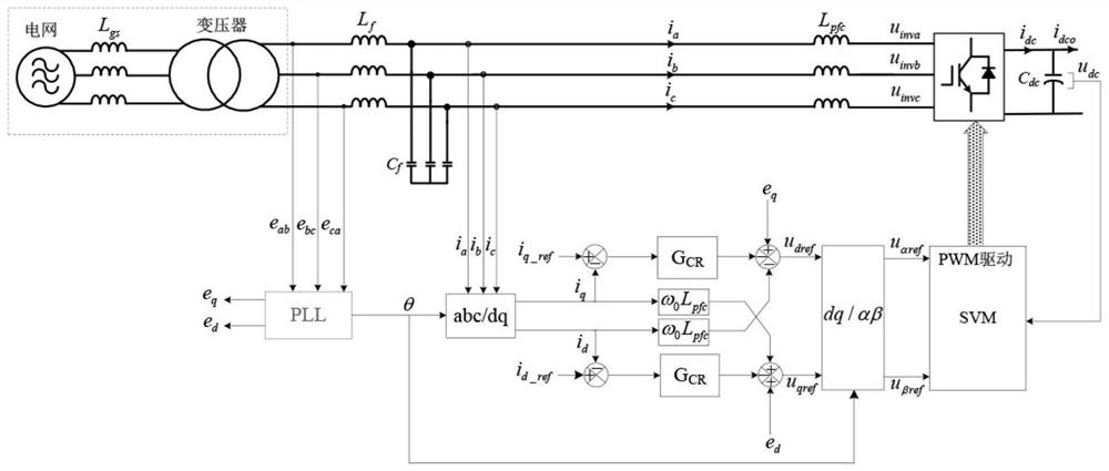
technical field [0001] The present application relates to the technical field of power electronics, in particular to a control method and system for eliminating the frequency coupling effect of a phase-locked loop of a grid-connected device. Background technique [0002] In recent years, with the rapid development of new energy and the widespread use of power electronic devices in the power generation, transmission, distribution, and consumption of power systems, the grid-connected characteristics of the grid-connected devices and the interaction stability with the grid are affected. It has attracted widespread attention, especially in the context of weak power grids, and the related stability issues are more prominent. [0003] Such as figure 1 As shown, the current grid-connected devices generally adopt the vector control framework based on phase-locked loops. Wu Xiangqiang et al. proposed in the literature "Sequence Impedance Model of Three-phase Grid-connected Inverter...

Claims


Application Information

Patent Timeline
Patent Type & Authority Applications(China)
IPC IPC(8): H02J3/38H02M7/04H02M1/08H02M1/12
CPCH02J3/38H02M7/04H02M1/08H02M1/12
Inventor 周党生陈佳明
Owner SHENZHEN HOPEWIND ELECTRIC CO LTD
Learn More