
Eureka
For R&D, Eureka makes reading and utilizing patents & technical documents easy.
Eureka AIR
Designed for self-driven R&D workflows. Generate viable solutions, solve complex R&D challenges, empower your innovation with AI.

Eureka Materials
Designed for material experts only. Revolutionize your material R&D, from search, analyze, to developing new materials.

TechResearch
Generate reliable direction feasibility study reports for your R&D in just a few steps.

TechSeek
Discover and master advanced knowledge NOW. Basics, ideas, possibilities, all at once.

TechMind
As an expert in R&D Theories, TechMind can generates customized viable solutions instantly.

TechRisk
Analyze your overall solution with one click, know your potential R&D risks in advance.

TechMonitor
Get weekly tech updates, stay abreast of the latest tech innovations and key insights.
Machining supporting device for DD motor
A support device and motor technology, applied in the field of motor processing, can solve the problems of workpiece damage, easy residual dust, noise, etc.
- Summary
- Abstract
- Description
- Claims
- Application Information
AI Technical Summary
Problems solved by technology
Method used
Image

Examples
Embodiment 1
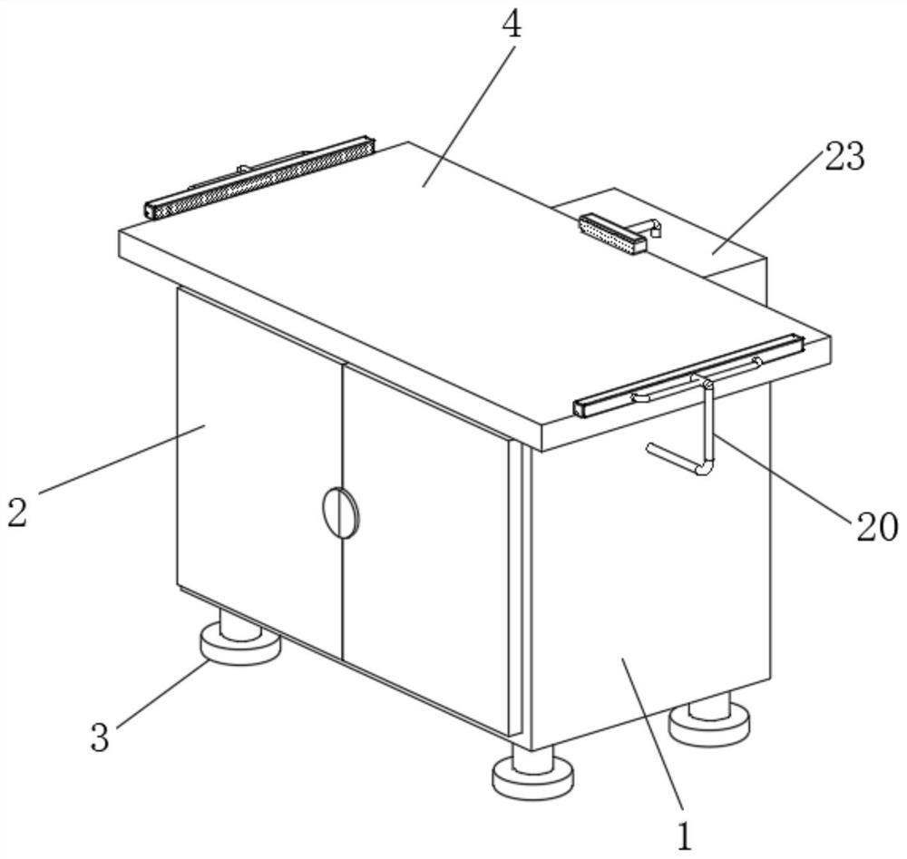
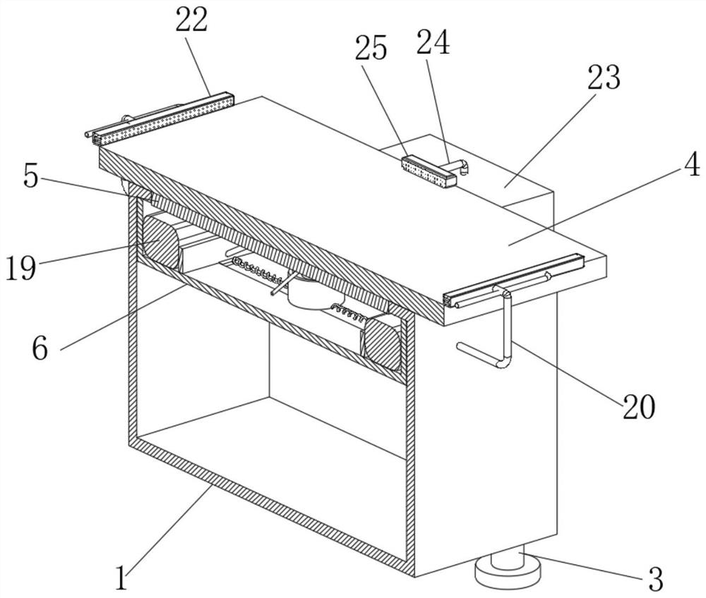
[0029] see Figure 1-8 , the present invention provides a technical solution: a processing support device for DD motors, including a support cabinet 1, the outer wall of the support cabinet 1 is hinged with a cabinet door 2, the bottom outer wall of the support cabinet 1 is fixedly connected with a support column 3, and supports The top outer wall of the cabinet 1 is provided with an operating table 4, and the bottom outer wall of the operating table 4 is fixedly connected with a fixed block 5. The inner wall of the shock box 6 is movably connected, the inner wall of the support cabinet 1 is fixedly connected with a shock absorber 6, the outer wall of the bottom of the fixed block 5 is fixedly connected with a first movable push rod 7, and the bottom of the inner wall of the shock absorber 6 is fixedly connected with a fixed column 8 , the end of the first movable push rod 7 away from the fixed block 5 is fixedly connected with an extruding block 9, and the bottom of the inner...
Embodiment 2
[0032] see Figure 3-7 As shown, on the basis of Embodiment 1, the present invention provides a technical solution: the outer wall of the bottom of the fixed block 5 is movably connected with a second movable push rod 14, and the bottom of the inner wall of the shock-absorbing box 6 is provided with a sliding groove 15, and the sliding groove The inner wall of 15 is slidably connected with sliding block 16, and the end of the second movable push rod 14 away from fixed block 5 is movably connected with the outer wall of sliding block 16, and the outer wall of one side of sliding block 16 is fixedly connected with extrusion plate 17, and sliding block 16 is away from A second spring 18 is arranged between one side of the outer wall of the extruding plate 17 and the outer wall of the fixed column 8, and the second spring 18 is arranged between the inner walls of the slide groove 15, and both sides of the inner wall of the shock absorbing box 6 are fixedly connected with airbags. ...
Embodiment 3
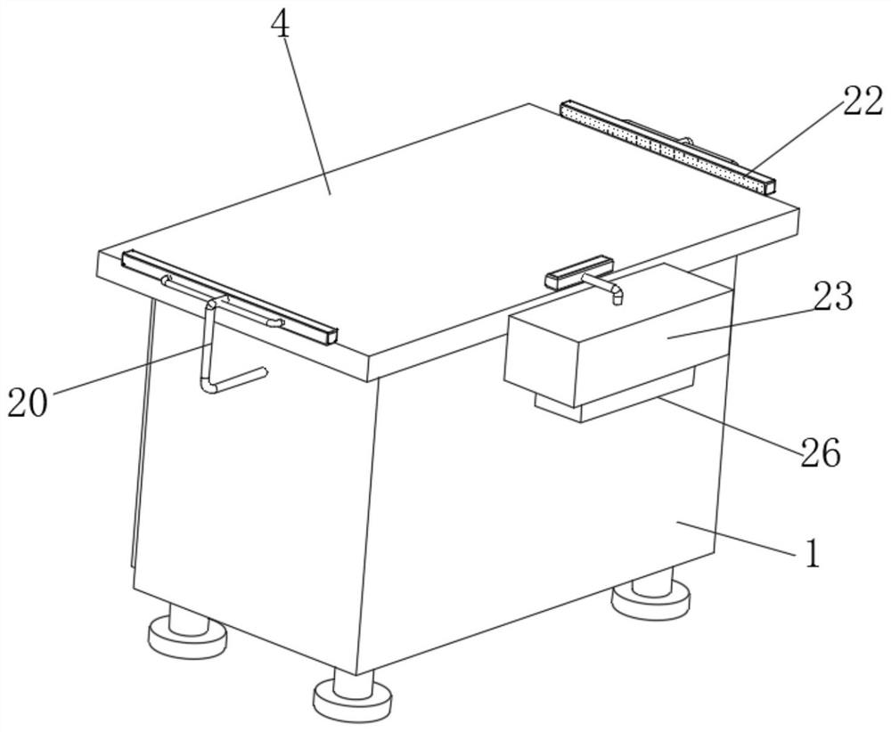
[0035] see Figure 1-5 As shown, on the basis of Embodiment 1 and Embodiment 2, the present invention provides a technical solution: the inner wall of the airbag 19 is interspersed with an air outlet pipe 20, and the outer walls on both sides of the air outlet pipe 20 are fixedly connected with air distribution pipes 21, The end of the trachea 20 away from the air bag 19 is fixedly connected to the nozzle 22, the end of the air distribution pipe 21 away from the air outlet pipe 20 is fixedly connected to the inner wall of the nozzle 22, the outer wall of the nozzle 22 is provided with an air outlet, and the outer wall of the support cabinet 1 is fixedly connected to the side away from the front. There is a first dust collecting box 23, the inner wall of the first dust collecting box 23 is fixedly connected with a fan, the inner wall of the fan is fixedly connected with a dust suction pipe 24, and the end of the dust suction pipe 24 away from the fan is fixedly connected with a ...
PUM
 Abstract
Description
Claims
Application Information
 - R&D Engineer
- R&D Manager
- IP Professional
- Industry Leading Data Capabilities
- Powerful AI technology
- Patent DNA Extraction
Browse by: Latest US Patents, China's latest patents, Technical Efficacy Thesaurus, Application Domain, Technology Topic, Popular Technical Reports.
© 2024 PatSnap. All rights reserved.Legal|Privacy policy|Modern Slavery Act Transparency Statement|Sitemap|About US| Contact US: help@patsnap.com