
CO2 monitoring system for suffocation case

A monitoring system, CO2 technology, applied in general control system, control/regulation system, program control in sequence/logic controller, etc., can solve the problems of intelligence, low degree of automation, unstable concentration of suffocation pit, etc. To ensure the quality of meat and improve the efficiency of slaughtering

Active Publication Date: 2021-09-07
青岛建华食品机械制造有限公司
View PDF8 Cites 0 Cited by
  • Summary
  • Abstract
  • Description
  • Claims
  • Application Information

AI Technical Summary

Problems solved by technology

[0003] The technical problem to be solved in the present invention is: overcome the CO 2 Intelligent gas concentration control and low degree of automation lead to CO 2 The defect of unstable concentration provides a CO2 monitoring system for the stunner box, which can automatically control the CO2 in the stun pit 2 concentration, and keep the CO in the asphyxiation pit 2 The concentration is stable, while improving the slaughtering efficiency, it also ensures the meat quality after slaughtering

Method used


Image

  • CO2 monitoring system for suffocation case
  • CO2 monitoring system for suffocation case
  • CO2 monitoring system for suffocation case

Examples


Embodiment approach 1

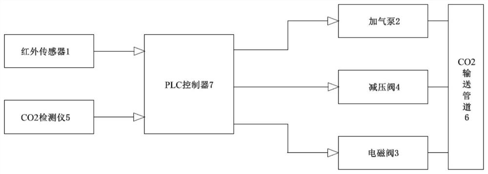
[0025] Implementation mode 1: if figure 1 As shown, the CO2 monitoring system of the stun case includes an infrared sensor 1, an air pump 2, a solenoid valve 3, a pressure reducing valve 4, a CO 2 Detector 5, CO 2 Delivery pipeline 6, PLC controller 7, the infrared sensor 1, air pump 2, solenoid valve 3, pressure reducing valve 4, CO 2 Detector 5, CO 2 The conveying pipelines 6 are all electrically connected to the PLC controller 7, wherein the infrared sensor 1 is arranged in the suffocation pit for detecting CO in the suffocation pit. 2 concentration; the gas pump 2 is set at CO 2 The inlet end of the delivery pipeline 6 is used to supply CO 2 Delivery pipeline 6 is pumped into CO for asphyxiation 2 ; The solenoid valve 3 is set at CO 2 The gas outlet end of the delivery pipeline 6 is used to convert CO 2 CO for asphyxiation in delivery pipeline 6 2 into the suffocation pit; the pressure relief valve 4 is arranged on the CO at the upstream end of the electromagnetic ...

Embodiment approach 2

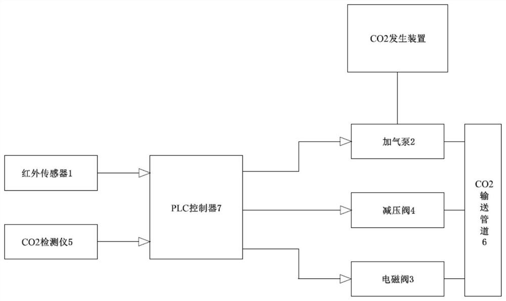
[0026] Implementation mode 2: if figure 2 shown, to achieve CO 2 Occurrence supply, this stun chassis CO 2 The air pump 2 in the monitoring system is externally connected to a CO 2 generating device. In order to realize the supply into CO 2 The concentration adjustment of the conveying pipeline, the CO 2 monitoring system for the CO 2 The generating device is connected with the output end of the PLC controller 7 . The rest of the structures and components are the same as those in Embodiment 1 and will not be described again.

Embodiment approach 3

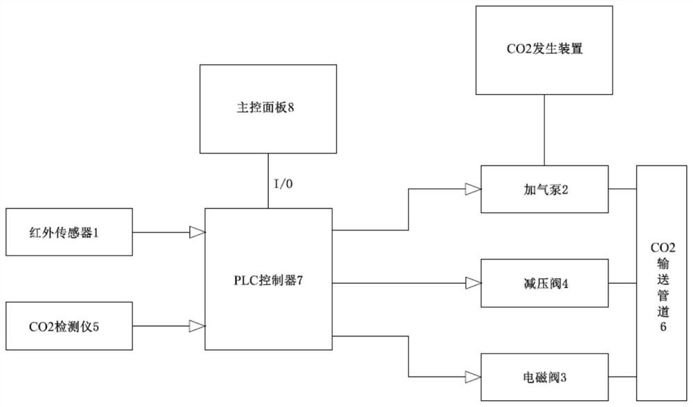
[0027] Implementation mode 3: if image 3 As shown, in order to realize the external asphyxiation pit, CO 2 CO in the pipeline 2 Concentration monitoring data display, manual intervention control, and modification of PLC prefabricated programs, the CO 2The PLC controller 7 of the monitoring system is connected to a main control panel 8 through an I / O interface, and the main control panel 8 includes a display screen, control buttons and an editing keyboard. The rest of the structures and components are the same as those in Embodiment 1 and will not be described again.


PUM


Abstract

The invention relates to a CO2 monitoring system for a suffocation case. The CO2 monitoring system for the suffocation case comprises an infrared sensor, a gas adding pump, an electromagnetic valve, a pressure reducing valve, a CO2 detector, a CO2 conveying pipeline and a PLC; the infrared sensor, the gas adding pump, the electromagnetic valve, the pressure reducing valve, the CO2 detector and the CO2 conveying pipeline are all electrically connected with the PLC, wherein the infrared sensor is arranged in a suffocation pit; the gas adding pump is arranged at the gas inlet end of the CO2 conveying pipeline; the electromagnetic valve is arranged at the gas outlet end of the CO2 conveying pipeline; the pressure reducing valve is arranged on the CO2 conveying pipeline at the upstream end of the electromagnetic valve; and the CO2 detector is arranged on the CO2 conveying pipeline at the upstream end of the pressure reducing valve. The CO2 monitoring system for the suffocation case can automatically control the CO2 concentration in the suffocation pit and keep the CO2 concentration in the suffocation pit stable, so that the slaughtering efficiency is improved, and the meat quality after slaughtering is ensured.

Description

technical field [0001] The invention relates to the technical field of monitoring, in particular to a CO 2 surveillance system. Background technique [0002] The stunning machine is a CO 2 Equipment for slaughtering pigs by gas asphyxiation. When the existing suffocation machine is used to suffocate pigs, the internal environment is a sealed structure. After the pigs are driven into the cage, they are sent down to the suffocation pit. There is a high concentration of CO in the suffocation pit. 2 , the pig is output after being stunned. Existing stunning machines for CO in the stunning pit 2 Intelligent gas concentration control and low degree of automation lead to CO 2 The concentration is unstable, which directly affects the slaughter efficiency, as well as the meat quality and the color of the internal organs of the slaughtered pork. Contents of the invention [0003] The technical problem to be solved in the present invention is: overcome the CO 2 Intelligent gas...

Claims


Application Information

Patent Timeline
Patent Type & Authority Applications(China)
IPC IPC(8): G05B19/05
CPCG05B19/054G05B2219/1103Y02A50/20
Inventor 殷彩红杨华建孙胜斌郭嘉昊马转红高扬
Owner 青岛建华食品机械制造有限公司
Learn More