Device and method for installing collector ring of generator of wind turbine generator

A technology for installing devices and wind turbines, which is applied in the manufacture of motor generators, wind power generation, electromechanical devices, etc., and can solve the problems of damaged collector rings, difficult repairs, and unfavorable protection.

Pending Publication Date: 2021-09-07
HEBEI SUNTIEN NEW ENERGY TECH
View PDF0 Cites 0 Cited by
  • Summary
  • Abstract
  • Description
  • Claims
  • Application Information

AI Technical Summary

Problems solved by technology

[0002] The quality of the generator in the wind turbine is closely related to the assembly of its accessories. There are two copper slip rings in the commutator of the generator, which are called collector rings. The rotor of the generator is a steel shaft with rolling wires. The production During the process, there is an error between the outer diameter of the shaft and the inner diameter of the collector ring. If the interference of the press-fitting size is large, the collector ring will be damaged, and if the interference is small, it will cause loosening.
In addition, in the process of pressing the collector ring, the uneven pressure used will also cause the collector ring to not be accurately installed on the generator shaft, causing the assembly to be stuck or not strong
[0003] Large parts such as collector rings in wind turbines need to be replaced regularly. When the collector rings are replaced and installed, due to the influence of the space of the fan, the installation of the collector rings is difficult, laborious and laborious, and it is easy to cause damage
There is no professional device for daily disassembly of collector rings, which makes disassembly difficult and seriously affects work efficiency
[0004] In the prior art, the fixed hole of the generator shaft is used to place the collector ring on the disc connected with the screw thread, and the collector ring is brought into the generator shaft through the thread. In this connection, the collector The pushing force of the ring acts on the generator shaft, and the fixed stress point of the collector ring is concentrated on the fixed screw on the generator shaft. Due to the large shape of the generator and the collector ring of the wind turbine, after a period of use, it is easy to make The thread on the screw and the generator shaft is damaged, resulting in unstable fixation of the collector ring, and the threaded hole on the generator shaft is not easy to repair after damage
In addition, three stress points are used for installation. During the loading process, the collector ring is prone to deviation due to excessive force on one side. After deviation, the installation of the collector ring is more laborious. inconvenient
[0005] In the prior art, most of the slip rings are pressed into the generator shaft by means of tooling push-in, and such tooling cannot be used when the slip rings are disassembled, so that the utilization rate of the tooling is low, and because the slip ring inside the slip ring There is an interference fit between the hole and the generator shaft, the disassembly work is more difficult than the assembly work, and sometimes the collector ring will be damaged, resulting in waste of workpiece materials
[0006] The existing tooling for assembling the collector rings does not protect the collector rings. Due to the small disassembly space in the wind turbine unit, it is easy to cause bumps or damage to the outside of the collector rings during the assembly of the collector rings, which is not conducive to protection.

Method used


Image

  • Device and method for installing collector ring of generator of wind turbine generator
  • Device and method for installing collector ring of generator of wind turbine generator
  • Device and method for installing collector ring of generator of wind turbine generator

Examples


Embodiment 2

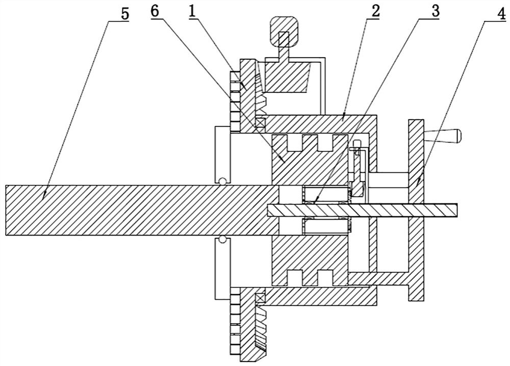
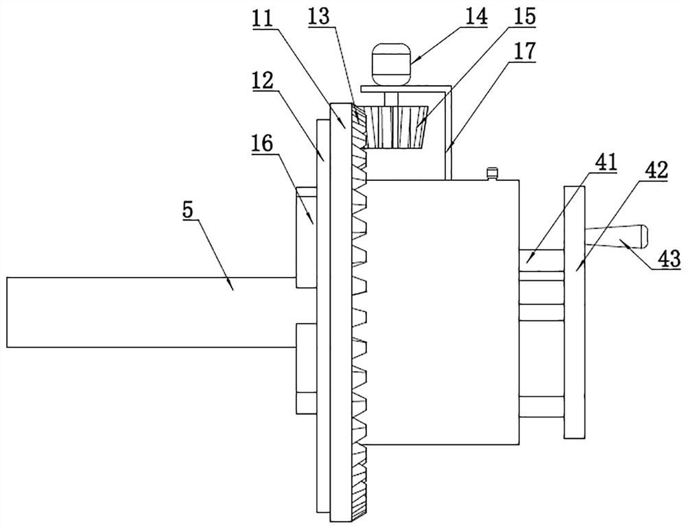
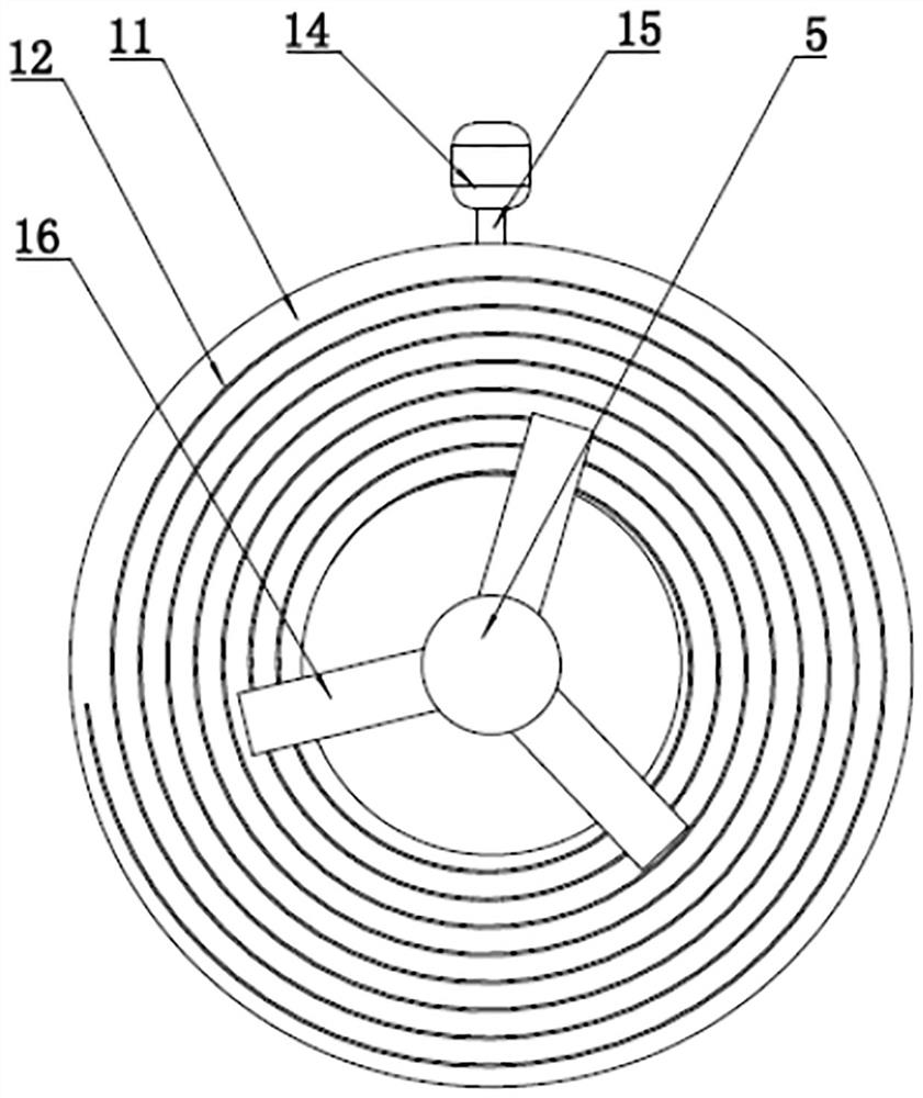
[0128] Such as Figure 7 As shown, a generator slip ring installation device for a wind power generating set includes a centering device 1, a sheath 2 fixedly connected to the centering device 1, and a push-off device fixedly connected to one side of the sheath 2 4 and the cylinder 44 fixedly connected to the pushing device 4; the centering device 1 is provided with a through hole; the sheath 2 is set on the collector ring 6; the centering device 1 and the The sheath 2 is coaxial; the collector ring 6 is provided with a support device 3 at one end; the support device 3 is fixedly connected to the sheath 2 through a connecting shaft 312; the cylinder 44 is fixed on the base of the generator on the stand,

[0129] The support device 3 is coaxial with the sheath 2 ; the centering device 1 is sleeved on the generator shaft 5 .

[0130] The difference from Embodiment 1 is that the handle 43 is cancelled, the fixed shaft 37 is cancelled, and the supporting device 3 is fixed on the...


PUM


Abstract

The invention provides a collector ring mounting device for a generator of a wind generating set. The collector ring mounting device is convenient to assemble and disassemble and simple in structure. The device is characterized in that the device comprises a centering device, a sheath, a pushing and disassembling device and a handle, wherein one end of the sheath is rotationally connected to the centering device, the pushing and disassembling device is arranged on one side of the sheath, and the handle is fixedly connected to the pushing and disassembling device; the centering device is provided with a through hole; the protective sleeve is arranged on the collecting ring in a sleeving manner; the centering device and the sheath are coaxial; a supporting device is arranged at one end of the collecting ring; the supporting device penetrates through the sheath and is in sliding connection with the sheath; the supporting device is in threaded connection with the pushing and unloading device; the supporting device and the sheath are coaxial; and the centering device is sleeved on the generator shaft. By adopting the centering device, the repeated centering work of assembling, loading and then pulling out caused by difficult assembling in interference fit and inaccurate centering in the assembling process is avoided, the working time is shortened, and the working efficiency is improved.

Description

technical field [0001] The invention belongs to the technical field of auxiliary tools for installing generators of wind turbines, and in particular relates to a collector ring installation device and method for generators of wind turbines. Background technique [0002] The quality of the generator in the wind turbine is closely related to the assembly of its accessories. There are two copper slip rings in the commutator of the generator, which are called collector rings. The rotor of the generator is a steel shaft with rolling wires. The production During the process, there is an error between the outer diameter of the shaft and the inner diameter of the collector ring. If the press-fit size interference is large, the collector ring will be damaged, and if the interference is small, it will cause loosening. Moreover, in the process of press-fitting the slip ring, the uneven pressure used will also cause the slip ring to not be accurately installed on the generator shaft, ca...

Claims


Application Information

Patent Timeline
IPC IPC(8): H02K15/00
CPCH02K15/00Y02E10/72
Inventor 梅春晓张二辉刘润龙吴楠苏伟
Owner HEBEI SUNTIEN NEW ENERGY TECH
Why Eureka
Try Eureka