Land supporting structure for green building

A green building and support structure technology, applied in the field of land support structures, can solve problems such as unfavorable plant growth, water source deterioration, and plant rot

Inactive Publication Date: 2021-09-10
华新建工集团有限公司 +1
View PDF7 Cites 3 Cited by
  • Summary
  • Abstract
  • Description
  • Claims
  • Application Information

AI Technical Summary

Problems solved by technology

[0003] In green buildings, planted roofs are usually used to cover a greening form of the building roof. In the current technology, sometimes the water source cannot be replenished in time and the plants die, and after multiple waterings, the excess water will be stored in the The bottom of the planting pot, when the planting pot body is blocked, the excess water cannot be discharged from the planting pot in time, which will cause the root of the plant to rot. However, some water storage devices in the prior art are mostly non-flowing, and during the long-term water storage process Deterioration of medium water sources is not conducive to plant growth

Method used


Image

  • Land supporting structure for green building
  • Land supporting structure for green building
  • Land supporting structure for green building

Examples


Embodiment 1

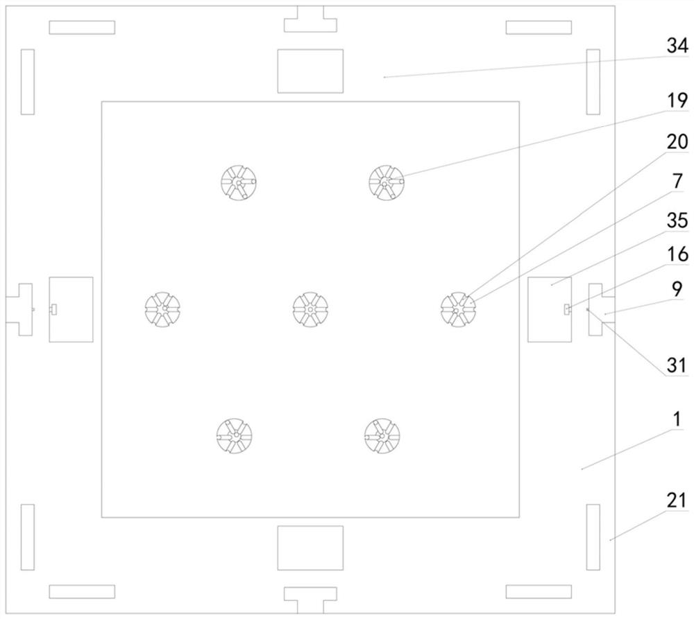
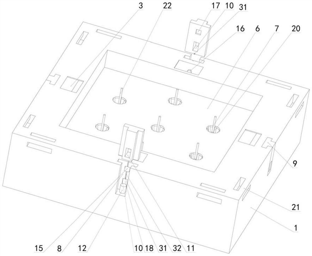
[0028] Embodiment 1, a ground support structure for green buildings, including a plurality of basins 1, the basins 1 are in the shape of a cube, the basins 1 are horizontally provided with water retaining boards 2, and the water retaining boards 2 separate the inside of the basins 1 The overflow tank 3 and the water storage chamber 4 are divided into upper and lower parts. The overflow tank 3 is placed above the water storage chamber 4. A plurality of overflow ports 5 are provided on the water retaining plate 2. The overflow tank 3 and the water storage chamber 4 are overflowed. The outlet 5 is connected, and the top of the basin body 1 is provided with a baffle plate 34 matched with the overflow tank 3, the baffle plate 34 is used to cover the overflow tank 3, and reduces external pollution to the water source in the basin body 1, and the baffle plate 34 is provided with a A plurality of connecting grooves 8 correspond to a plurality of through holes 35 one by one. The existen...

Embodiment 2

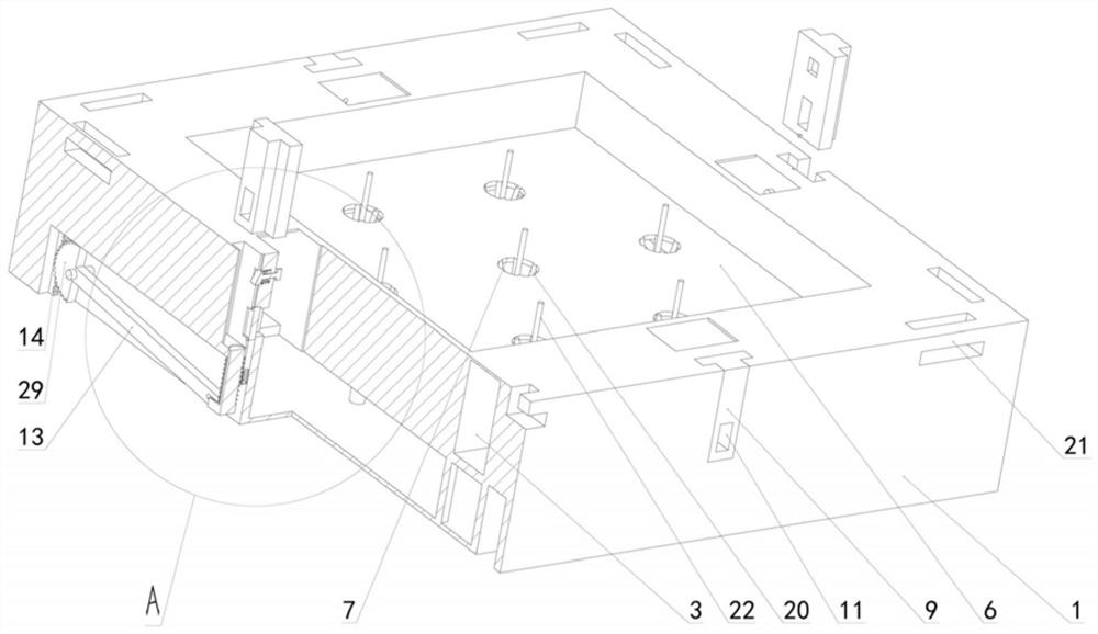
[0029] Embodiment 2. On the basis of Embodiment 1, the support mechanism includes a push rod 12, a gear connecting rod 13 and a rack 14. The push rod 12 vertically penetrates the bottom wall of the connecting groove 8, and the distance between the push rod 12 and the bottom wall of the connecting groove 8 is The space is vertically sealed and slidably connected. The first spring 27 placed between the lower end of the push rod 12 and the basin body 1 is coaxially sleeved on the top rod 12. One end 27 of the first spring is connected to the basin body 1. The other end of the first spring is connected to the basin body 1. One end is connected with the lower end of the push rod, the first spring 27 gives the push rod 12 a vertical upward pulling force, the basin body 1 is vertically slidably connected with racks 14 opposite to the two sides of the push rod 12, and the basin body 1 is rotatably connected with The sector gear 29 meshed with the rack 14, the gear connecting rod 13 is ...

Embodiment 3

[0030]Embodiment 3, on the basis of Embodiment 1, the limit mechanism includes a wedge block 15 and a connecting rod 16. The connecting rod 16 is arranged horizontally and runs through the basin body 1. One end of the connecting rod 16 is placed in the connecting groove 8 and connected to the wedge block. 15 is connected at one end, and the other end of the connecting rod 16 slides through the basin body 1 and is placed in the overflow tank 3. The connecting rod 16 is coaxially sleeved with a second spring 28 between the inner wall of the wedge-shaped block 15 and the basin body 1. One end of the second spring 28 is connected with the basin body 1, and the other end of the second spring 28 is connected with the wedge block 15, and the second spring 28 gives the wedge block 15 a thrust away from the basin body 1. Matching slot 17, when the connecting block 9 is inserted into the connecting slot 8, the connecting block 9 will squeeze the wedge block 15 and drive the connecting ro...


PUM


Abstract

The invention relates to a land supporting structure for a green building. The land supporting structure comprises a plurality of pot bodies, water baffles are arranged on the pot bodies, each water baffle divides the inner side of the corresponding pot body into an upper part and a lower part, namely, an overflow tank and a water storage cavity, the overflow tank is arranged above the water storage cavity, a plurality of overflow ports are formed in each water baffle, and the overflow tank communicates with the water storage cavity through the overflow ports; and vertical planting pots are arranged on the water baffles, water absorption cotton threads are arranged on the planting pots, and a water injection mechanism and a discharge outlet are arranged on each pot body. According to the land supporting structure for the green building, disassembly is convenient, the activity of water in the pot bodies is improved, growth of plants is facilitated, meanwhile, the problem that plants die due to the fact that water sources of the multiple pot bodies are not uniform is solved, and the problem that excessive water received in the pot bodies cannot be discharged in time is solved.

Description

technical field [0001] The invention relates to the technical field of green buildings, in particular to a ground support structure for green buildings. Background technique [0002] Green building refers to the maximum saving of resources in the whole life cycle of the building, including energy saving, land saving, water saving, material saving, etc., to protect the environment and reduce pollution, to provide people with healthy, comfortable and efficient use of space, and to be in harmony with nature. Symbiotic buildings increase the effective green area of ​​the city. [0003] In green buildings, planted roofs are usually used to cover a greening form of the building roof. In the current technology, sometimes the water source cannot be replenished in time and the plants die, and after multiple waterings, the excess water will be stored in the The bottom of the planting pot, when the planting pot body is blocked, the excess water cannot be discharged from the planting p...

Claims


Application Information

Patent Timeline
Patent Type & Authority Applications(China)
IPC IPC(8): A01G9/02A01G27/06
CPCA01G9/02A01G27/06
Inventor 傅仕海周存清吉峰李雪祥王鑫
Owner 华新建工集团有限公司
Why Eureka
Try Eureka