Device for soaking parts in anti-rust oil

A technology of anti-rust oil and parts, applied in the field of parts processing, can solve the problems of time-consuming, difficult to clean, cumbersome operation steps, etc.

Active Publication Date: 2021-09-10
南通豪派金属制品有限公司
View PDF11 Cites 4 Cited by
  • Summary
  • Abstract
  • Description
  • Claims
  • Application Information

AI Technical Summary

Problems solved by technology

[0004] However, in the actual working process, we found that the steps of using the device are to put the parts into the screen frame first, then put the parts into the oil-immersed space through the hoisting structure, and then put them into the oil-immersed space through the hoisting structure. Take out the screen frame from the structure, move the parts to the structure where the oil is drained, drain the oil, and finally move the screen frame to the original position. The overall operation steps are relatively cumbersome. time, and the oil attached to the screen frame is easy to drip onto the surface of the device, which is not easy to clean, so how to optimize this step and improve the overall oil immersion effect is what we need to consider

Method used


Image

  • Device for soaking parts in anti-rust oil
  • Device for soaking parts in anti-rust oil
  • Device for soaking parts in anti-rust oil

Examples


Embodiment 1

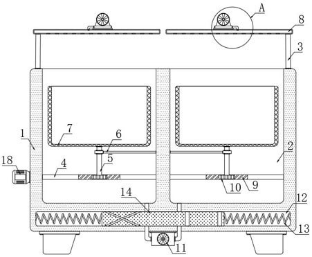
[0031] refer to Figure 1-5 , a device for immersing parts in antirust oil, comprising a housing 1, two treatment tanks 2 are symmetrically arranged on the upper end of the housing 1, and a screen frame 7 is arranged in each treatment tank 2, and the upper end surface of each screen frame 7 Openings are all provided, and mounting frame 6 is installed on the inwall of each treatment tank 2, and the lower end of each screen frame 7 is fixedly connected with vertical rod 5, and the lower end of each vertical rod 5 is connected with the corresponding mounting frame 6. Rotationally connected, the lower end of each vertical rod 5 runs through the corresponding mounting frame 6 and is fixedly connected to the worm wheel 10, and the inner walls on both sides of each treatment tank 2 are connected with a rotating rod 4 in rotation, and each rotating rod 4 is provided with Match the thread layer 9 with the corresponding worm wheel 10, the thread layer 9 is similar to the thread on the w...

Embodiment 2

[0041] refer to Figure 6-8 , the difference between this embodiment and Embodiment 1 is that each rotating rod 4 is sleeved with two sleeves 19, and the inner wall of each sleeve 19 is provided with a slider 21, and each rotating rod 4 There are chute 23 that cooperates with the slider 21, and one side of each slider 21 is elastically connected with the inner wall of one side of the corresponding chute 23 through the vibration spring 22, and the outer wall of each sleeve 19 is fixed A plurality of stirring rods 20 are connected, and magnetic plates 24 are embedded on the inner walls of both sides of each treatment tank 2 , and one of the stirring rods 20 on each sleeve 19 is made of iron.

[0042] In this embodiment, the rotation of the two rotating rods 4 will drive a plurality of sleeves 19 to rotate, thereby causing a plurality of stirring rods 20 to rotate. During the oil immersion process, the stirring of the stirring rods 20 can further disturb the water body and increa...


PUM


Abstract

The invention discloses a device for soaking parts in anti-rust oil. The device comprises a shell, two treatment grooves are symmetrically formed in the upper end of the shell, a net frame is arranged in each treatment groove, a mounting frame is mounted on the inner wall of each treatment groove, the lower end of each net frame is fixedly connected with a vertical rod, the lower end of each vertical rod is rotationally connected with the corresponding mounting frame, the lower end of each vertical rod penetrates through the corresponding mounting frame and is fixedly connected with a worm wheel, and a rotating rod is rotationally connected between the inner walls of the two sides of each treatment groove. According to the device, through the arrangement of the two net frames, oil draining and oil soaking can be achieved synchronously, the net frames do not need to be moved many times, the situation that oil attached to the net frames drips all around is avoided while the oil soaking step is optimized, the overall oil soaking and oil draining efficiency is further improved through the arrangement of fans, and therefore the effect of improving the overall machining efficiency is achieved.

Description

technical field [0001] The invention relates to the field of parts processing, in particular to a device for soaking parts in antirust oil. Background technique [0002] After the finished parts are manufactured, they are generally treated with anti-rust treatment to avoid rusting and scrapping the parts. Now factories generally apply anti-rust oil to the parts manually, but the efficiency of manual oiling is too low, so it is necessary to design a Mechanical oiling is used to solve this problem; [0003] In this regard, the Chinese invention patent with the application number CN201810419405.7 discloses "a device for soaking anti-rust oil for auto parts", including a bottom plate, a soaking box, a vertical plate, a top plate, a frame body, a lower hopper, an annular plate, and a mesh plate , the first sliding rail, the first slider, the first bearing seat, screw rod, etc.; the soaking box is installed on the left side of the top of the bottom plate, the vertical plate is in...

Claims


Application Information

Patent Timeline
Patent Type & Authority Applications(China)
IPC IPC(8): B05C3/09B05C3/04B05C13/00B05C11/10B05D3/04
CPCB05C3/09B05C3/04B05C13/00B05C11/10B05D3/0406
Inventor 许鹏
Owner 南通豪派金属制品有限公司
Why Eureka
Try Eureka