
Forming and processing equipment for exhaust fume collecting hood of kitchen range hood

A technology for forming processing and fume collecting hoods, which is applied in the direction of metal processing equipment, drilling/drilling equipment, metal processing machinery parts, etc., and can solve the problem of shifting of fume collecting hoods, increasing the processing steps of opening holes, and pushing the holes where holes cannot be opened. Problems such as squeezing limit to achieve the effect of avoiding high temperature

Inactive Publication Date: 2022-08-09
崔文霞
View PDF1 Cites 0 Cited by
  • Summary
  • Abstract
  • Description
  • Claims
  • Application Information

AI Technical Summary

Problems solved by technology

[0004] The forming processing equipment usually fixes the fume collecting hood manually before opening the fume collecting hood. Because the surface of the fume collecting hood is relatively smooth, the drill bit will impact the fume collecting hood during the process of opening the fume collecting hood, which may easily cause The displacement of the fume collection hood, which leads to the inability to quickly clamp and fix the fume collection hood before processing;
[0005] At present, CN202110220000.2 in the prior art is a forming and processing equipment for the fume collecting hood of kitchen and toilet range hood, which discloses forming and processing equipment. This invention reduces the applicability of the equipment and cannot push the hole when opening Squeeze the limit, and the hole is prone to bending, which reduces the effect of the hole. At the same time, the burrs after the hole cannot be polished, which increases the processing steps after the hole and reduces the efficiency of the hole. Moreover, it cannot be adjusted according to the number of required openings, thereby reducing the flexibility of the equipment and other issues;
[0006] The invention can mainly solve the problem that the fast clamping and fixing cannot be performed before the fume collecting hood is processed

Method used


Image

  • Forming and processing equipment for exhaust fume collecting hood of kitchen range hood
  • Forming and processing equipment for exhaust fume collecting hood of kitchen range hood
  • Forming and processing equipment for exhaust fume collecting hood of kitchen range hood

Examples


Embodiment 1

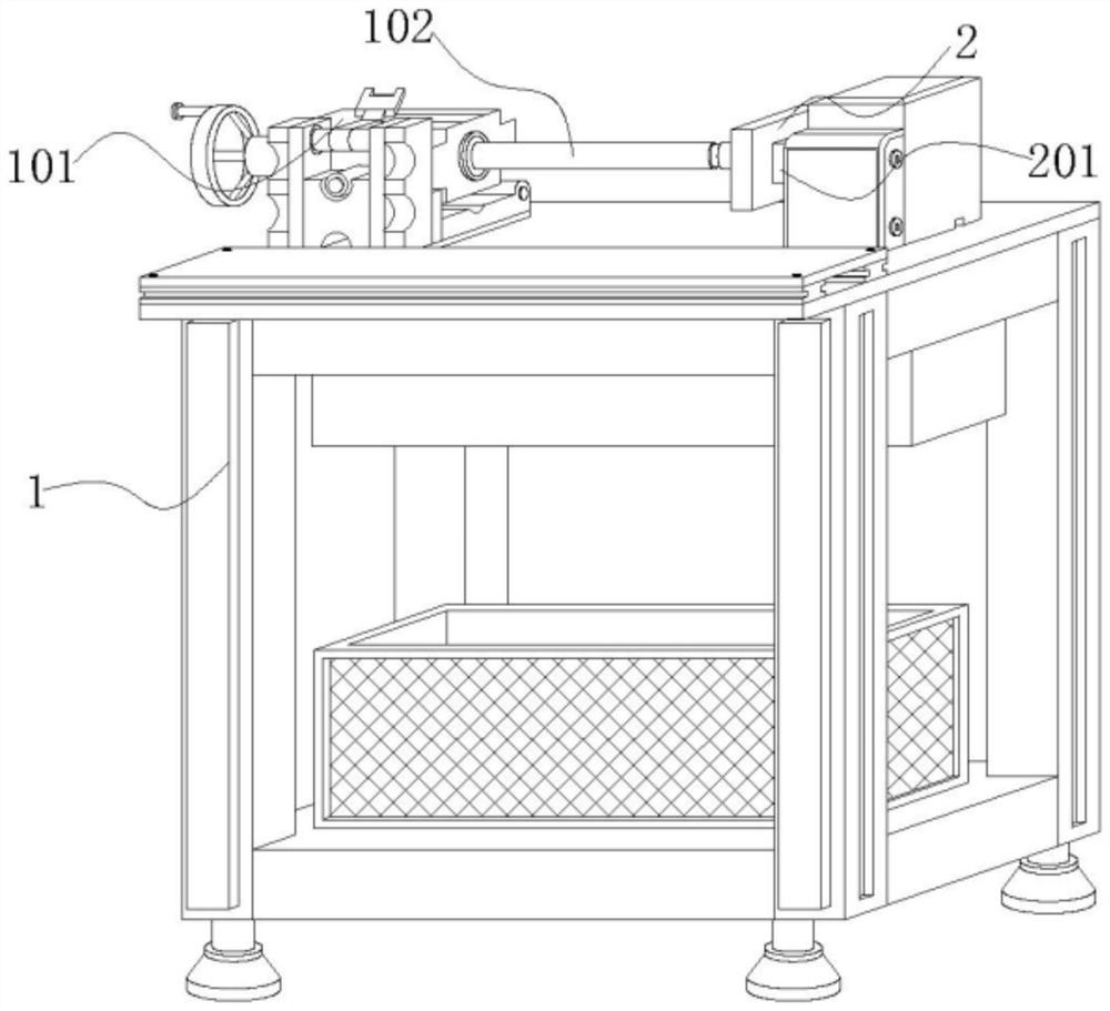
[0042] Embodiment 1: a kitchen range hood fume collecting hood forming processing equipment, including a hole punch 1, the hole end of the hole punch 1 is provided with a clamping mechanism and a hole assembly, wherein the hole assembly includes a motor 101 and a drill bit 102, the drill bit 102 rotates on the side of the clamping mechanism, and the clamping mechanism includes a bracket 2 and a sliding frame 201;

[0043] Wherein: the motor 101 and the drill bit 102, the motor 101 is electrically connected to the power supply through the power cord, the motor 101 drives the drill bit 102 to rotate at a high speed horizontally, and the drill bit 102 opens a hole inside the fume hood;

[0044] The bracket 2, the inside of the bracket 2 is arranged in a hollow shape, the bracket 2 and the drill bit 102 are arranged in a horizontal correspondence, the bracket 2 is arranged in a semi-circular arc shape near the inner wall of the sliding frame 201, and the semi-circular arc angle is ...

Embodiment 2

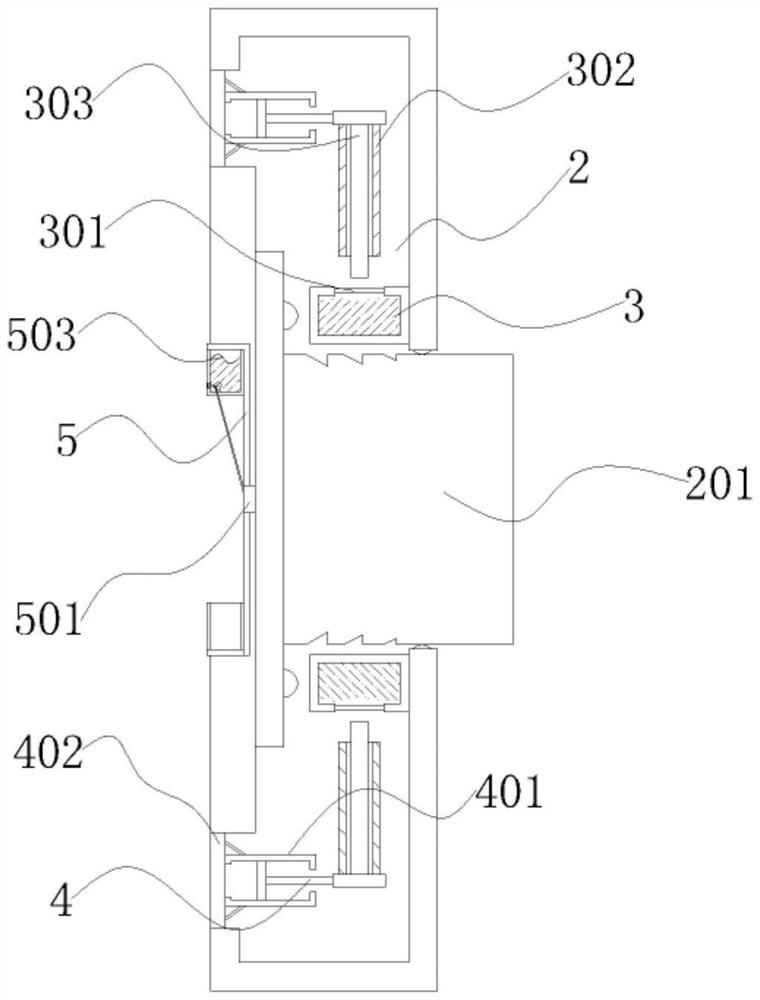
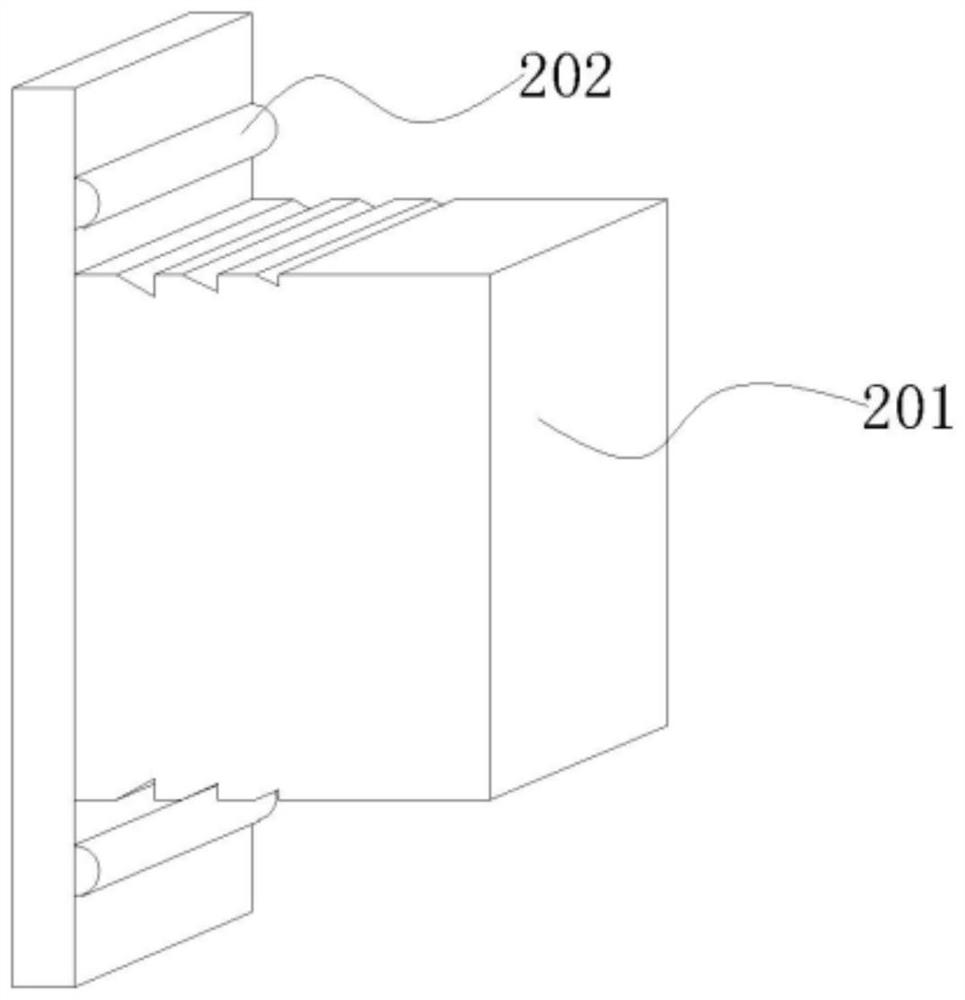
[0048] Embodiment 2: Referring to the drawings 2-5 in the description, it can be known that the difference between Embodiment 2 and Embodiment 1 is that the clamping mechanism includes a bump 202, a water bag 3, a deformation layer 301, a slide rail 302, a slide bar 303, The piston rod 4, the sleeve 401 and the adsorption layer 402, the bumps 202 are inlaid on both ends of the side of the sliding frame 201, the water bag 3 is inlaid on the inner wall of the bracket 2, the deformation layer 301 is inlaid on the inner wall of the water bag 3, and the slide rail 302 is inlaid Inside the bracket 2 , the sliding rod 303 slides and extends to both ends of the sliding rail 302 , the piston rod 4 slides on one end of the sliding rod 303 , the sleeve 401 is installed inside the bracket 2 , and the adsorption layer 402 slides and fits on the sleeve. side of 401;

[0049] Among them: the bump 202, the bump 202 and the side surface of the water bag 3 are horizontally slid and squeezed, an...

Embodiment 3

[0061] Embodiment 3: Referring to the accompanying drawings 6-8, it can be known that the difference between Embodiment 3 and Embodiments 1 and 2 is that the clamping mechanism includes a snap ring 5, a slider 501, a shaft arm 502, a water tank 503, and a rotating disk 6 , the sealing rod 601 and the disc 602, the snap ring 5 is embedded in the side of the bracket 2, the slider 501 slides through the inside of the snap ring 5, the shaft arm 502 is embedded in one side of the slider 501, the water tank 503 is installed on the snap ring 5 At one end of the interior, the rotary disk 6 swings inside the water tank 503, the sealing rod 601 swings on one side of the rotary disk 6, and the disk 603 runs through the side of the water tank 503;

[0062] Among them: the snap ring 5 and the slider 501, the snap ring 5 is arranged in a transverse concave shape, the slider 501 slides and extends to one side of the sliding frame 201, when the sliding frame 201 slides horizontally, the slider...


PUM

PropertyMeasurementUnit
thicknessaaaaaaaaaa

Abstract

A motor is electrically connected with a power source through a power line, the motor drives a drill bit to horizontally rotate at a high speed, the drill bit is used for drilling the interior of the exhaust fume collecting hood, the interior of a support is hollow, the support and the drill bit are horizontally and correspondingly arranged, and the inner wall, close to a sliding frame, of the support is in a semi-arc shape. The piston rod is arranged in the sleeve, the semi-arc angle is 180 degrees, the sliding frame is embedded in the inner side of the support in a sliding mode, the sliding frame is arranged in a transverse T shape, grooves are formed in the two ends of the sliding frame, and when one end of the piston rod slides in the sleeve and the piston rod moves outwards at the moment, the volume of only a small part of gas between the sleeve and the adsorption layer is increased, the gas pressure is reduced, and the external atmospheric pressure is not changed. The atmospheric pressure assists the adsorption layer to bend on the side face of the sleeve, the adsorption layer deforms integrally, and after the adsorption layer deforms, the surface of the exhaust fume collecting hood can be adsorbed and fixed, so that the clamping mechanism can quickly fix the surface of the exhaust fume collecting hood.

Description

technical field [0001] The invention relates to the technical field of range hood processing, in particular to a forming and processing equipment for a kitchen range hood hood. Background technique [0002] When the fume hood is processed, it is necessary to use weldment welding to form a weld seam at the weld, and the weld seam is polished and polished to form a seamless welded fume hood. After opening the hole, it is convenient for the fume hood to pass through the internal components of the range hood, which is convenient for the flow of oil fume, which is a technical inspiration for the forming and processing equipment; [0003] The research on molding equipment found the following problems: [0004] Before the fume collecting hood is opened, the forming processing equipment usually fixes the fume collecting hood manually. Since the surface of the fume collecting hood is relatively smooth, the drill bit will impact the fume collecting hood during the opening process of ...

Claims


Application Information

Patent Timeline
Patent Type & Authority Applications(China)
IPC IPC(8): B23B41/00B23B47/00B23Q3/00B23Q11/10
CPCB23B41/00B23B47/00B23Q3/00B23Q11/10B23Q2703/10
Inventor 崔文霞
Owner 崔文霞
Learn More