Side turning die for forming lap joint part of automobile top cover and stamping method of side turning die

A technology of automobile roof and lap joint, which is applied in the directions of forming tools, vehicle parts, manufacturing tools, etc., can solve the problems of unable to meet welding requirements, single, unable to guarantee the consistency of R1 angle, etc.

Pending Publication Date: 2021-09-10
DONGFENG LIUZHOU MOTOR
View PDF12 Cites 0 Cited by
  • Summary
  • Abstract
  • Description
  • Claims
  • Application Information

AI Technical Summary

Problems solved by technology

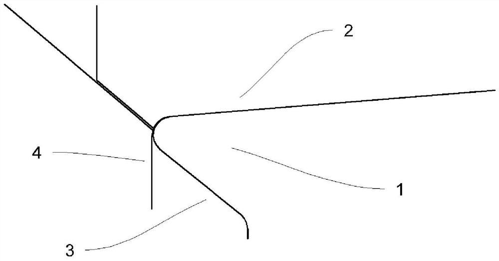
As a 3D processing area, when the machining tool is processing the punch fillet (corresponding to the part fillet R1), it is prone to vibration, which will distort the processed punch fillet and cause a large error, which affects the punch The accuracy of the fillet R1 of the stamped top cover cannot guarantee that the R1 angle is completely consistent with the product in theory, and the entire R1 angle is easily distorted in three-dimensional space, and it cannot be guaranteed that it is an R angle with a single curvature. It is difficult to produce a top cover that meets the precision requirements of laser welding
[0005] 2) The direction of the existing side shaping knife block is completely processed according to the side shape of the top cover, without pre-springback treatment. After the top cover is formed, due to the springback characteristics of the material, there is a tendency to return to the original state, that is, springback occurs , resulting in the top cover accuracy being too poor, unable to meet the welding requirements
[0006] 3) There is no special research and preparation for the boundary of the existing binder plate, and there is no control, so when the existing binder plate is overpressed, it is easy to cause secondary edge defects

Method used


Image

  • Side turning die for forming lap joint part of automobile top cover and stamping method of side turning die
  • Side turning die for forming lap joint part of automobile top cover and stamping method of side turning die
  • Side turning die for forming lap joint part of automobile top cover and stamping method of side turning die

Examples


Embodiment Construction

[0031] The specific implementation manners of the present invention will be further described in detail below in conjunction with the accompanying drawings and embodiments. The following examples are used to illustrate the present invention, but are not intended to limit the scope of the present invention.

[0032] In describing the present invention, it should be understood that the terms "upper", "lower", "front", "rear", "left", "right", "vertical", "horizontal", The orientations or positional relationships indicated by "top", "bottom", "inner", "outer", etc. are based on the orientations or positional relationships shown in the drawings, and are only for the convenience of describing the present invention and simplifying the description, rather than indicating or implying the It should not be construed as limiting the invention that a device or element must have a particular orientation, be constructed, and operate in a particular orientation.

[0033] In the description ...


PUM

PropertyMeasurementUnit
Radiusaaaaaaaaaa

Abstract

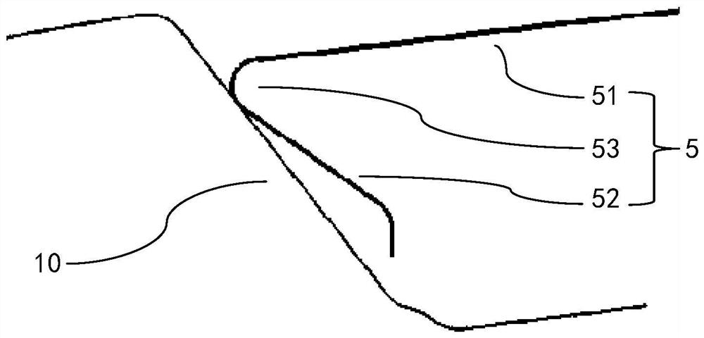
The invention relates to the technical field of manufacturing of metal parts of automobile bodies in white, and discloses a side turning die for forming a lap joint part of an automobile top cover and a stamping method. The lap joint part comprises a top plate, a side plate and a welding fillet, and the side turning die comprises a male die, a pressing plate and a side shaping cutter block. The male die comprises a male die top face, a male die connecting face and a male die side face, wherein the male die connecting face is arranged in a receding mode relative to the welding fillet; and in the side flanging process, the side turning die does not make direct contact with a transition plate of an intermedium part, the transition plate is naturally deformed and further bent to form the welding fillet through feeding of the side shaping cutter block, and therefore the welding fillet is formed. With the side turning die for forming the lap joint part of the automobile top cover and the stamping method, it can be guaranteed that the welding fillet of the lap joint part of the automobile top cover has the same radius in the three-dimensional space, it is guaranteed a laser welding tailored blank is a curve with one single curvature, and the attractiveness of a top plate is not affected while the laser welding precision is improved.

Description

technical field [0001] The invention relates to the field of automobile body sheet metal parts manufacturing, in particular to a stamping method of an automobile roof and a mold thereof. Background technique [0002] With the maturity of laser welding technology, more and more car body roofs are welded by laser. The use of laser welding instead of traditional spot welding can make the appearance of the car more beautiful, save the decorative strips needed in the resistance spot welding process, reduce the welding procedure, and greatly reduce the cost while increasing the welding strength; but due to laser focus The post-spot size is small and the weld seam is narrow. Welding requires high assembly accuracy of the weldment, and the position of the beam on the workpiece cannot be significantly shifted. If the assembly accuracy of the workpiece or the positioning accuracy of the beam cannot meet the requirements, it is easy to cause welding defects. [0003] At present, the ...

Claims


Application Information

Patent Timeline
IPC IPC(8): B21D37/10B21D19/08B21D53/88
CPCB21D37/10B21D19/08B21D53/88
Inventor 唐竞雷玉霞廖勇韦旺华孙光辉陈文刚王文军许诺
Owner DONGFENG LIUZHOU MOTOR
Why Eureka
Try Eureka