
Polishing and detecting method for injection-molded rearview mirror shell

A detection method and rearview mirror technology, which is applied in the direction of grinding machines, grinding machine parts, grinding/polishing equipment, etc., can solve the problems of unsatisfactory grinding effect and grinding efficiency, low degree of automation, and low production efficiency.

Inactive Publication Date: 2021-09-10
李显辉
View PDF0 Cites 0 Cited by
  • Summary
  • Abstract
  • Description
  • Claims
  • Application Information

AI Technical Summary

Problems solved by technology

The existing technology, firstly, the degree of automation is not high, and manpower is still required to check and polish one by one; secondly, the lack of corresponding grinding tools makes the grinding effect and grinding efficiency unsatisfactory
Third, the grinding process and testing process are carried out in batches, and the production efficiency is not high
Fourth, the lack of corresponding flying dust protection devices makes the working environment poor

Method used


Image

  • Polishing and detecting method for injection-molded rearview mirror shell
  • Polishing and detecting method for injection-molded rearview mirror shell
  • Polishing and detecting method for injection-molded rearview mirror shell

Examples


Embodiment Construction

[0035] The following are specific embodiments of the present invention and in conjunction with the accompanying drawings, the technical solutions of the present invention are further described, but the present invention is not limited to these embodiments.

[0036]In the description of the present invention, it should be noted that the orientation or positional relationship indicated by the terms "inner", "lower", etc. is based on the orientation or positional relationship shown in the drawings, or the conventionally placed position when the product of the invention is used. Orientation or positional relationship is only for the convenience of describing the present invention and simplifying the description, and does not indicate or imply that the referred device or element must have a specific orientation, be constructed and operated in a specific orientation, and thus should not be construed as a limitation of the present invention. In addition, the terms "first", "second", e...


PUM


Abstract

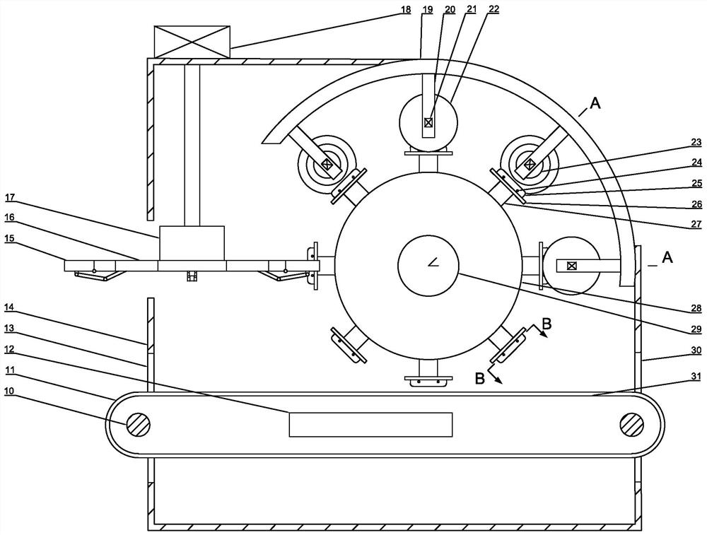
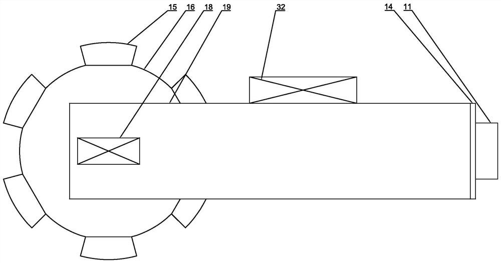
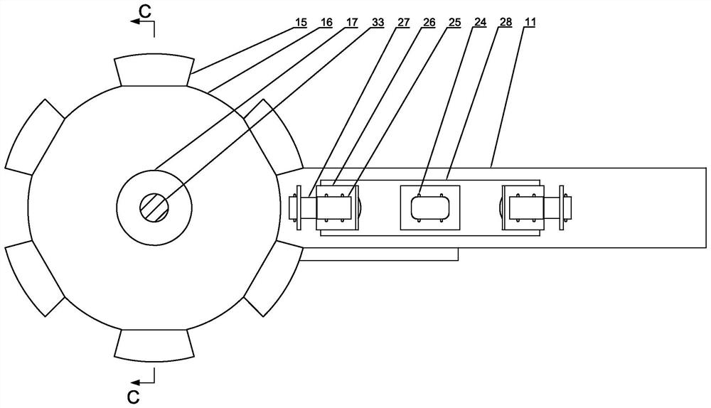
The invention belongs to the field of plastic product production, and particularly relates to a polishing and detecting method for an injection-molded rearview mirror shell. The method is carried out by being matched with a polishing and detecting device for the injection-molded rearview mirror shell. The polishing and detecting device comprises a machine body, a shell motor and a shell rotating shaft are arranged outside the machine body, a shell roller is arranged on the shell rotating shaft, eight shell supporting columns are evenly distributed on the outer circumferential face of the shell roller, and a shell control mechanism is arranged on each shell supporting column; a conveying mechanism is arranged on the lower portion of the machine body, and a pressure mechanism is arranged on the inner side of the conveying mechanism; the machine body is provided with an arc-shaped machine body shell, and four sets of polishing supports and polishing and detecting mechanisms are evenly arranged on the inner arc face of the arc-shaped machine body shell at 45 degrees; and a turning plate stepping motor is arranged on the upper portion of the machine body, a turning plate rotating shaft is arranged at the output end of the turning plate stepping motor and provided with a turning plate connecting plate, a turning plate controller is evenly provided with six turning plate mandrels at 60 degrees, each turning plate mandrel is connected with a turning plate, and a control mechanism is arranged between the turning plate connecting plate and each turning plate.

Description

technical field [0001] The invention belongs to the field of plastic product production, and in particular relates to a grinding and testing method for an injection-molded rearview mirror shell. Background technique [0002] Injection molded rearview mirror housing is an important component of the car. After the injection molding of the rearview mirror housing is completed, it needs to be inspected for quality. The outer surface of the injection molded rearview mirror housing with qualified quality and no structural defects is processed and polished to facilitate subsequent hardening and painting processes. In the existing technology, firstly, the degree of automation is not high, and manpower is still required to check and polish one by one; secondly, there is a lack of corresponding grinding tools, which makes the grinding effect and grinding efficiency unsatisfactory. The 3rd, polishing process and testing process are carried out in batches, and production efficiency is...

Claims


Application Information

Patent Timeline
IPC IPC(8): B24B19/22B24B27/00B24B49/10B24B55/06B24B1/00
CPCB24B19/22B24B27/0076B24B27/0092B24B49/10B24B55/06B24B1/00
Inventor 不公告发明人
Owner 李显辉
Learn More