Prefabricated assembled pier and connecting method thereof

A prefabricated assembly and pier technology, which is applied in erecting/assembling bridges, bridges, bridge construction, etc., can solve problems such as unguaranteed grouting quality, decreased ductility, and project quality risks

Active Publication Date: 2021-09-10
TONGJI UNIV
View PDF14 Cites 1 Cited by
  • Summary
  • Abstract
  • Description
  • Claims
  • Application Information

AI Technical Summary

Problems solved by technology

However, the joint position of prefabricated piers is its natural weak point, which often leads to the concentration of damage and destruction
A large number of experimental studies on bridge piers connected by grouting sleeves have confirmed that compared with cast-in-place bridge piers, their ductility is reduced by 10% to 30% under the same reinforcement conditions, so it is not recommended to be used in strong earthquake areas. Limit the development and application of prefabricated assembly technology
The ductility of the grouted bellows is better than that of the grouted sleeve, but even the grouted bellows can only be approximately equal to the ductility of the cast-in-place pier
[0004] In addition, the joints of all prefabricated assembled bridge piers are also vulnerable parts of structural durability. A large number of experiments have confirmed that the joints of various types of new and old concrete are also convenient intrusion channels for various types of

Method used


Image

  • Prefabricated assembled pier and connecting method thereof
  • Prefabricated assembled pier and connecting method thereof
  • Prefabricated assembled pier and connecting method thereof

Examples


Embodiment 1

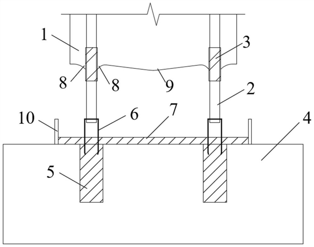
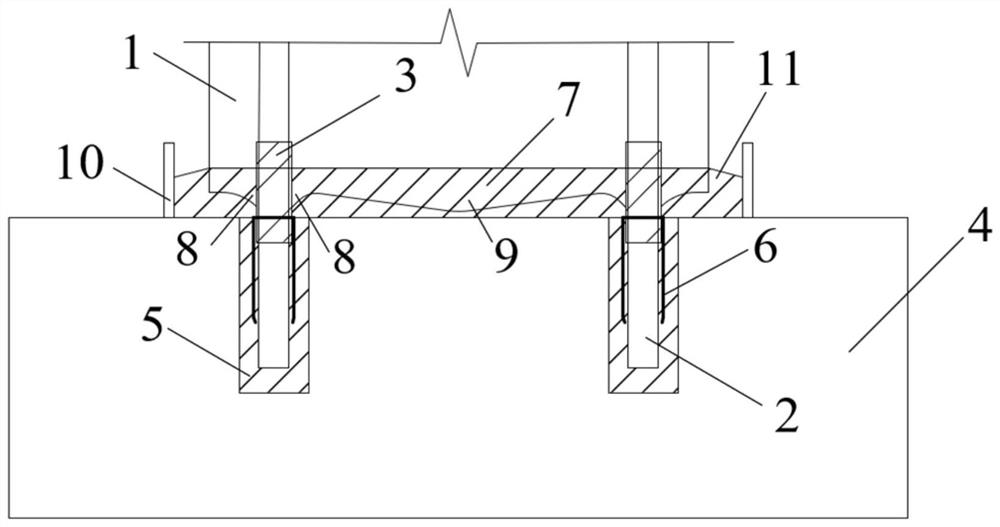
[0042] A prefabricated assembled bridge pier, such as figure 1 and figure 2 As shown, it includes the pier column 1 and the cap 4. The main reinforcement 2 is pre-embedded in the pier column 1. The main reinforcement 2 protrudes from the bottom of the pier column 1 for a certain length. In the pier column 1, the other part is exposed on the part where the main reinforcement 2 protrudes from the pier column 1, and the bottom of the pier column 1 is reserved at the center with a large cone 9 protruding toward the cap 4. The bottom of the pier column 1 A small cone 8 protruding toward the cap 4 is reserved at the root of the main rib 2, and the protruding length of the large cone 9 is greater than that of the small cone 8;

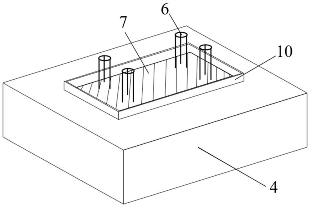
[0043] A grouting bellows 5 is pre-embedded in the bearing platform 4, the top of the grouting bellows 5 is flush with the top surface of the bearing platform 4, and a guiding device 6 is inserted in the grouting bellows 5, and the guiding device 6 is used ...


PUM


Abstract

The invention relates to a prefabricated assembled pier and a connecting method thereof, a main reinforcement is wrapped with a sleeve, one part of the sleeve is pre-buried in a pier column, the other part of the sleeve is inserted into a bearing platform along with the main reinforcement, a non-bonding section formed by the sleeve can enable strain of the main reinforcement to be evenly distributed in a section of area, the deformability of the main reinforcement is remarkably improved, and then the ductility of the pier column is improved; the sleeve crosses a new and old concrete interface of the pier column and the bearing platform, erosive substances can be blocked or the path length of the erosive substances to the main reinforcement is prolonged, and the corrosion resistance and durability of the structure are remarkably improved; a grouting corrugated pipe is pre-buried in a bearing platform, when the pier column is connected with the bearing platform, grouting is conducted in the grouting corrugated pipe firstly, concrete slurry is slightly higher than the top face of the bearing platform to form a bedding layer, when the pier column falls, the main reinforcement is inserted into the grouting corrugated pipe under guiding of a specific guiding device, and the bottom of the pier column is compactly connected with the bedding layer; the main reinforcement is compactly connected with concrete slurry in the grouting corrugated pipe, so that the slurry jacking process is avoided, the construction process is simplified, and the construction efficiency is improved.

Description

technical field [0001] The invention relates to the technical field of bridge construction, in particular to a prefabricated assembled bridge pier and a connection method thereof. Background technique [0002] Bridge piers are important load-bearing components supporting bridge structures and are crucial to the safety of bridge structures. Bridge piers are often designed to produce plastic hinges at the bottom of the pier to improve the overall seismic performance of the bridge structure. In recent years, the prefabricated assembly technology of bridge pier structures has developed rapidly, which has greatly improved the efficiency of the construction site and effectively improved the construction environment. [0003] Grouting sleeves and grouting bellows connections are two commonly used connection methods for prefabricated piers. For example, the Chinese invention patent with the publication number CN106869017A discloses a prefabricated assembled pier with a flexible laye...

Claims


Application Information

Patent Timeline
IPC IPC(8): E01D19/02E01D19/00E01D21/00
CPCE01D19/02E01D19/00E01D21/00
Inventor 管仲国卢峻锐王雨杰
Owner TONGJI UNIV
Why Eureka
Try Eureka