
Accessory transmission structure

A technology of accessory transmission and transmission mechanism, which is applied in the direction of engine components, engine starting, machine/engine, etc., and can solve problems such as heavy weight of the casing, failure to meet the requirements of the transmission system, unreasonable design and layout, etc.

Active Publication Date: 2021-09-10
CHINA HANGFA SOUTH IND CO LTD
View PDF6 Cites 4 Cited by
  • Summary
  • Abstract
  • Description
  • Claims
  • Application Information

AI Technical Summary

Problems solved by technology

[0004] The invention provides an accessory transmission structure to solve the technical problem that the existing transmission device has unreasonable design and layout, which leads to heavy weight of the casing and does not meet the requirements of the transmission system

Method used


Image

  • Accessory transmission structure
  • Accessory transmission structure

Examples


Embodiment Construction

[0026] The embodiments of the present invention will be described in detail below with reference to the accompanying drawings, but the present invention can be implemented in various ways defined and covered below.

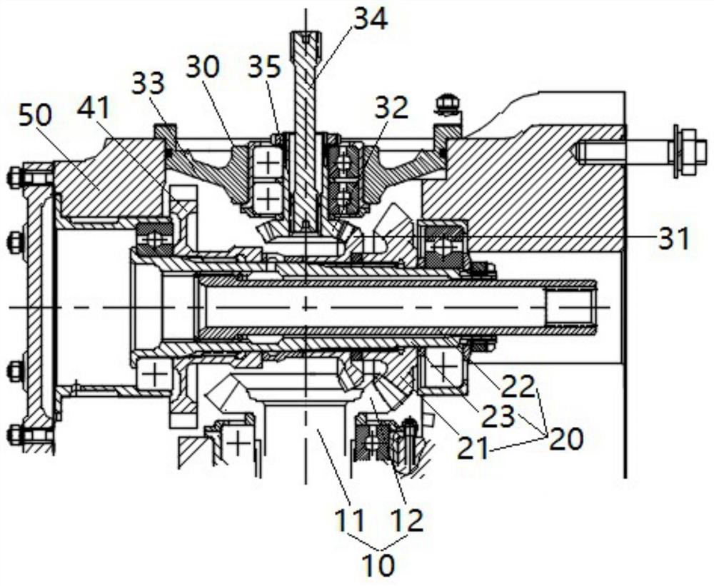
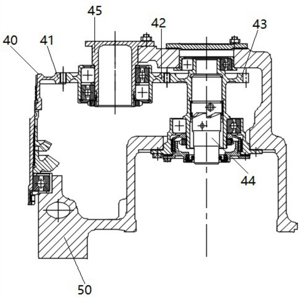
[0027] refer to figure 1 with figure 2 , the preferred embodiment of the present invention provides an accessory transmission structure, including: a speed governor, an oil mist separator, two starter motors, a power input transmission mechanism 10 for inputting power, and a drive mechanism for driving the speed governor. The governor transmission mechanism 20, the oil mist separator transmission mechanism 30 for driving the oil mist separator, and the starter motor transmission mechanism 40 for driving the two starter motors to operate separately, the governor, the oil mist separator, And two starter motors are respectively connected on the casing casing 50. The power input transmission mechanism 10 is arranged along a straight line, and its power input end is...


PUM


Abstract

The invention discloses an accessory transmission structure. The accessory transmission structure comprises a speed regulator, an oil mist separator, two starting motors, a power input transmission mechanism, a speed regulator transmission mechanism, an oil mist separator transmission mechanism and a starting motor transmission mechanism. The power input transmission mechanism is arranged along a straight line, and the power input end of the power input transmission mechanism is connected with a middle transmission mechanism in the case shell. The speed regulator transmission mechanism is perpendicular to and connected with the power input transmission mechanism. The oil mist separator transmission mechanism and the starting motor transmission mechanism are sequentially arranged in the axial direction of the speed regulator transmission mechanism, and the oil mist separator transmission mechanism is perpendicularly connected with the speed regulator transmission mechanism. The starting motor transmission mechanism is symmetrically arranged about the axis of the speed regulator transmission mechanism, and the two power output ends of the starting motor transmission mechanism are connected with the starting motors on the corresponding sides in the axial direction. By designing the accessory transmission structure, normal work of the interior of the case and an accessory transmission system can be achieved, and meanwhile the accessory can be compactly installed on the case shell.

Description

technical field [0001] The invention relates to the field of aero-engine transmission systems, in particular to an accessory transmission structure. Background technique [0002] When designing a certain type of aeroengine transmission system, multiple accessories are required to be installed on the casing, and each accessory needs to be designed for transmission. In order to reduce the outer dimensions of the case casing, thereby reducing the weight of the casing and meeting the transmission requirements, it is necessary to set the transmission device to meet the requirements of the transmission system and achieve a compact structure. [0003] The design and layout of the existing transmission device are unreasonable, which cannot well meet the transmission requirements, and lead to heavy weight of the casing, which does not meet the requirements of the transmission system. Contents of the invention [0004] The invention provides an accessory transmission structure to s...

Claims


Application Information

Patent Timeline
Patent Type & Authority Applications(China)
IPC IPC(8): F02N11/00F02N11/04F02N15/02
CPCF02N11/04F02N15/02F02N11/006
Inventor 席莉娅王涛刘正强严红周娇君
Owner CHINA HANGFA SOUTH IND CO LTD
Learn More