Ion flame detection circuit and method

A detection circuit and ion flame technology, applied in the direction of combustion method, burner, combustion type, etc., can solve the problems of low flame detection sensitivity, poor grounding of the burner head, and reduced contact area of ​​the negative electrode

Active Publication Date: 2021-09-10
VATTI CORP LTD
View PDF6 Cites 0 Cited by
  • Summary
  • Abstract
  • Description
  • Claims
  • Application Information

AI Technical Summary

Problems solved by technology

Due to technological reasons, the burner mostly adopts a detachable structure, and the materials of the burner are also diversified, which leads to the problem of poor grounding of the burner after a period of use
This results in a double-electrode flame induction, but due to the reduced contact area of ​​the negative electrode, the flame detection sensitivity is reduced,

Method used


Image

  • Ion flame detection circuit and method
  • Ion flame detection circuit and method

Examples


Embodiment Construction

[0023] The present invention will be described in further detail below in conjunction with the embodiments and with reference to the accompanying drawings.

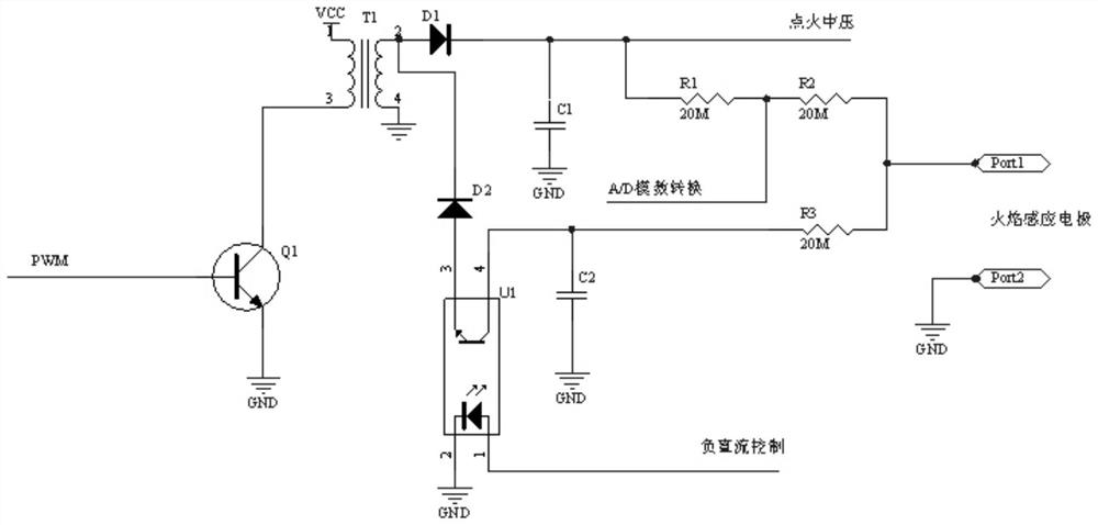
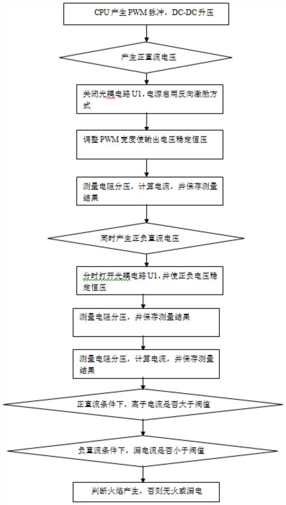
[0024] An ion flame detection circuit, reference Figure 1 to Figure 2 , including single-chip microcomputer, DC-DC unit, positive DC analog switch, negative DC analog switch, positive DC sampling unit, negative DC sampling unit, optocoupler circuit U1, detection circuit and CPU, CPU generates PWM pulse width modulation signal, DC -The DC unit changes the voltage and current output of the PWM pulse width through the positive DC analog switch and the negative DC analog switch; the single-chip microcomputer measures the flame equivalent resistance indirectly through the resistance divider to measure the ion current. The positive and negative DC-DC unit adopts the flyback switching power supply method to generate positive voltage. When the voltage is ignited, it is the input voltage of the ignition high voltage, and the high...


PUM


Abstract

The invention discloses an ion flame detection circuit and a method. The ion flame detection circuit comprises a single-chip microcomputer, a DC-DC unit, a positive direct-current analog switch, a negative direct-current analog switch, a positive direct-current sampling unit, a negative direct-current sampling unit, an optocoupler circuit U1, a detection circuit, and a CPU, wherein the CPU generates a PWM pulse width modulation signal, and the DC-DC unit changes the voltage and current output of the PWM pulse width through the positive direct-current analog switch and the negative direct-current analog switch; and the single-chip microcomputer measures flame equivalent resistance through resistance voltage division and indirectly measures ion current. The direct-current signal ion electric energy is adopted to eliminate the shunting effect of the stray capacitance, especially the influence of the stray capacitance of a burner on the sensitivity.

Description

technical field [0001] The invention relates to the technical field of gas stove ignition circuits, in particular to an ion flame detection circuit and method. Background technique [0002] Gas cookers use flame ion detection for flameout protection, and the contact area between the electrodes and the flame is related to the sensitivity of flame detection. Related studies have shown that the greater the contact area between the positive electrode and the flame, the higher the sensitivity of flame detection; and when the contact area reaches a certain value, the sensitivity of flame detection will no longer increase. Similarly, the larger the contact area between the negative electrode and the flame sensitivity is, the higher the flame detection sensitivity will be. When the contact area reaches a certain value, the flame detection sensitivity will no longer increase. At the same time, when the area of ​​the negative electrode is much larger than the area of ​​the positive e...

Claims


Application Information

Patent Timeline
IPC IPC(8): F23M11/04F23D14/72
CPCF23M11/045F23D14/725
Inventor 刘明雄潘叶江
Owner VATTI CORP LTD
Why Eureka
Try Eureka