Thermal infrared imager working temperature measuring device and focal plane self-adaptive compensation method

An infrared thermal imager and self-adaptive compensation technology, which can be used in measurement devices, radiation pyrometry, optical radiometry, etc.

Active Publication Date: 2021-09-10
KUNMING INST OF PHYSICS
View PDF7 Cites 1 Cited by
  • Summary
  • Abstract
  • Description
  • Claims
  • Application Information

AI Technical Summary

Problems solved by technology

[0007] On the one hand, it realizes high-precision and fast measurement of the internal working temperature of the infrared thermal imager, and provides real-time operating temperature for the internal temperature self-adaptation of the infrared thermal imager and external system operation users; on the other hand,

Method used


Image

  • Thermal infrared imager working temperature measuring device and focal plane self-adaptive compensation method
  • Thermal infrared imager working temperature measuring device and focal plane self-adaptive compensation method
  • Thermal infrared imager working temperature measuring device and focal plane self-adaptive compensation method

Examples


Embodiment 1

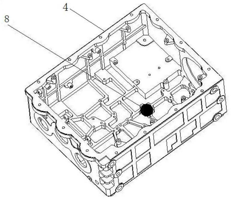
[0064] like figure 1 As shown, the transistor element used for temperature measurement is installed near the position of the internal focusing mirror of the infrared thermal imager 4, and one transistor element 8 can be installed to measure an operating temperature, and multiple transistors can also be installed at different positions where the temperature needs to be monitored. The element 8 is used to measure multiple temperatures, and this embodiment takes one temperature measurement as an example for illustration.

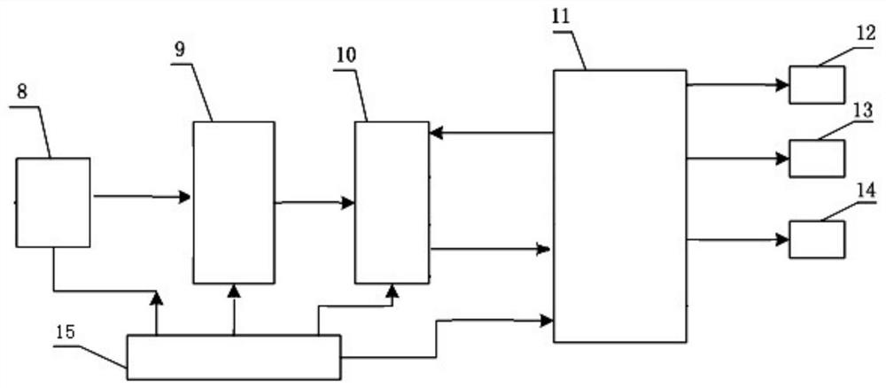
[0065] like figure 2 As shown, the infrared thermal imager operating temperature measuring device of the present invention consists of a transistor element 8, an operational amplification conditioning circuit 9, an analog-to-digital conversion circuit 10, a DSP digital signal processor 11, a memory module 12, an image display module 13, and a serial port communication module 14 and the power supply circuit 15 and so on.

[0066] The transistor element 8, the...

Embodiment 2

[0090] according to Figure 7 The flow chart of the present embodiment shown, at first, set up a set such as Figure 5 As shown in the calibration test environment, configure a thermostat 2 that can provide a simulated working environment temperature and has a thermostat observation window 3, and place the assembled infrared thermal imager 4 inside; observe in the thermostat outside the thermostat 2 A collimator 5 is arranged at the window 3 and placed on the shock-absorbing support work platform 6 , and a four-bar target simulation test target for testing the image performance of the infrared thermal imaging camera 4 is set on the collimator 5 . After the infrared thermal imager 4 is started to work, adjust the position of the infrared thermal imager 4 and the lens, and face the external collimator 5 through the observation window 3 of the thermostat, and the following will appear on the display: Image 6 The output video image shown is the observation image of 4 pairs of fo...


PUM


Abstract

The invention relates to a thermal infrared imager working temperature measuring device and a focal plane self-adaptive compensation method. The device is composed of a transistor element, an operational amplification conditioning circuit, an analog-to-digital conversion circuit, a DSP digital signal processor, a memory module, an image display module, a serial port communication module and a power supply circuit. The focal plane self-adaptive compensation method is based on real-time digital temperature information provided by a temperature measurement part, three-order fitting correction coefficients of all temperature intervals are stored after testing, and a temperature adaptive compensation focal plane function module adaptively optimizes and corrects the position of the infrared optical imaging focusing focal plane changing along with the temperature. The infrared optical imaging focusing plane position changing along with the temperature is adaptively optimized and adjusted based on the measured temperature value, the problems that imaging focusing is not clear enough, fuzzy and even cannot be used for imaging are solved, and the clear focusing imaging performance of the thermal infrared imager is improved.

Description

technical field [0001] The invention belongs to the technical field of infrared thermal imager measurement, and relates to an infrared thermal imager working temperature measurement device and a method for adaptively compensating a focal plane. Background technique [0002] At present, in the application field of infrared thermal imager, it is required that the thermal imager can adapt to various harsh environmental conditions, especially in the field of application of military infrared thermal imager, it is required The functional performance of the instrument meets the requirements of the weapon fire control platform system, and improves the long-distance precision strike combat capability of the fire control system. [0003] For a large and complex weapon system platform, it needs to work in an extreme temperature and harsh environment, and the existence of various heat sources will cause internal temperature rise, and the internal temperature is much higher than the work...

Claims


Application Information

Patent Timeline
IPC IPC(8): G01J5/00
CPCG01J5/00G01J2005/0077
Inventor 罗志斌杨帆蒋砾王志林李晶叶超朱洪洋郭小军杨有让沈志娟
Owner KUNMING INST OF PHYSICS
Why Eureka
Try Eureka