Automatic winding machine for inductance coil

An automatic winding machine and inductance coil technology, applied in coil manufacturing, inductance/transformer/magnet manufacturing, circuits, etc., can solve the problems of low clamping efficiency, difficult clamping and stable clamping, and uneven winding by manual operation.

Pending Publication Date: 2021-09-10
YAXIN (HUAIHUA) ELECTRONICS CO LTD
View PDF0 Cites 2 Cited by
  • Summary
  • Abstract
  • Description
  • Claims
  • Application Information

AI Technical Summary

Problems solved by technology

[0004] At present, in the actual processing of the inductance coil, it is necessary to wrap the cut raw materials with tape. The existing method is usually to achieve this operation manually, because it is necessary to stack multiple sheet materials together, so The following technical difficulties often exist in the actual production process: 1. Multiple sheets need to be loaded and transported. There is currently no suitable device on the market to realize this operation; 2. Multiple stacked sheet materials need to be efficiently transported. There are huge defects in the clamping operation and manual tape-wrapping operation, which is difficult to clamp stably, difficult to clamp, low clamping efficiency, and there is a huge quality risk of uneven winding and unstable processing quality in manual operation; 3. Multitasking There are some technical difficulties that are difficult to implement in the shipment and transportation of sheet-like materials, such as how to realize the connection of various processes, how to realize automatic feeding, automatic pushing, and subsequent stable transportation and uniform winding of winding induction tape; therefore, this paper The company independently developed a set of equipment to solve the above problems. In order to better apply for patent protection for this set of equipment, the company separately applied for patents for the clamping device, shipping device and the overall winding part of the sheet material for protection.

Method used


Image

  • Automatic winding machine for inductance coil
  • Automatic winding machine for inductance coil
  • Automatic winding machine for inductance coil

Examples


Embodiment Construction

[0030] In order to enable those skilled in the art to better understand the technical solution of the present invention, the present invention will be described in detail below in conjunction with the accompanying drawings. The description in this part is only exemplary and explanatory, and should not have any limiting effect on the protection scope of the present invention. .

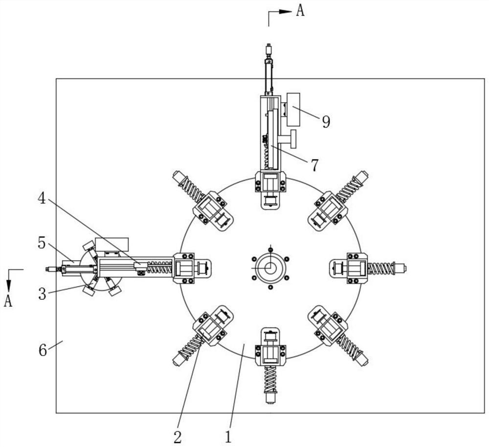
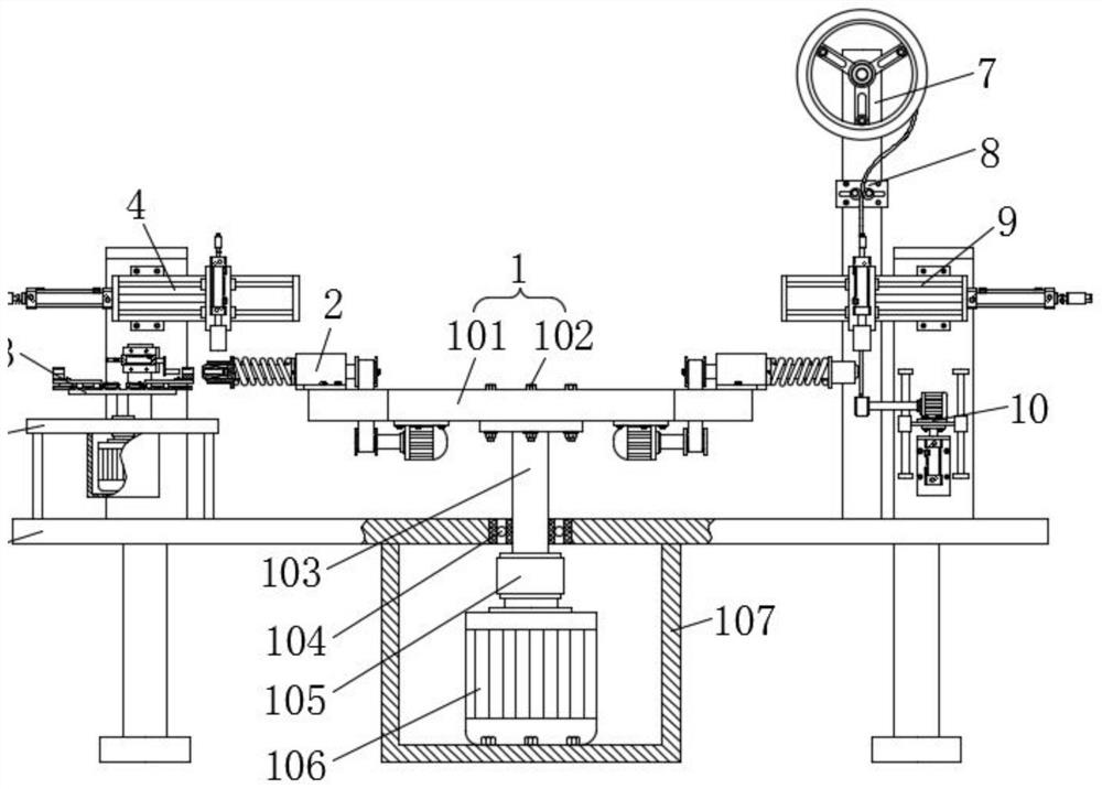
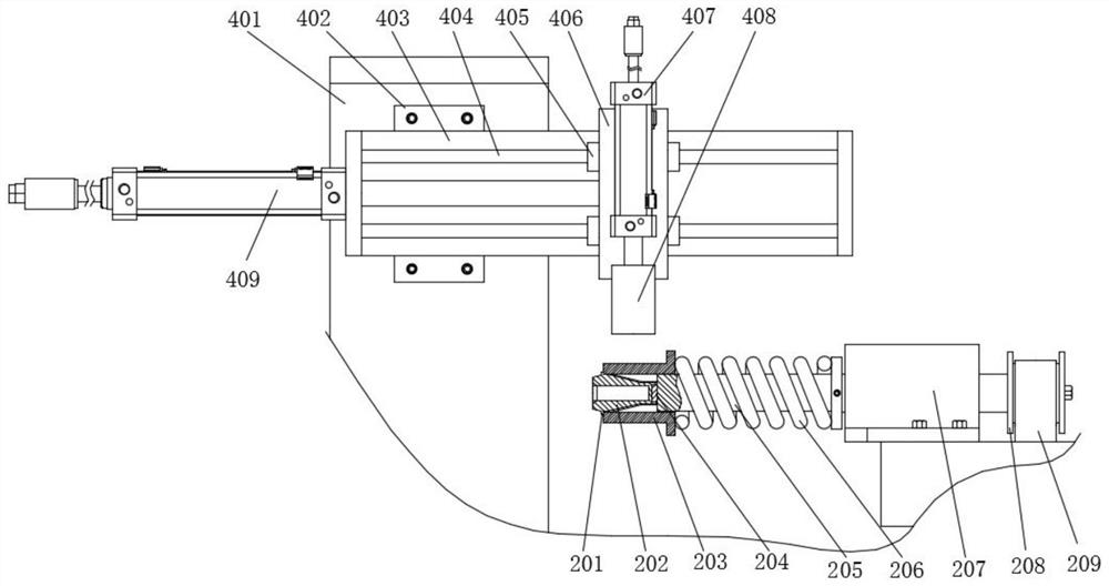
[0031] Such as Figure 1-Figure 6 As shown, the specific structure of the present invention is as follows: a turntable assembly 1 is included, and the turntable assembly 1 includes a turntable 101 capable of rotating. The turntable 101 is arranged in an annular array for clamping material clamping components 2. The clamping components 2- On the side and on the workbench 6, a first push sleeve assembly 4 matching with the clamping assembly 2 is provided, and a feeding assembly 3 for material pushing is arranged above the bracket seat 5 on one side of the workbench 6, and a feeding assembly 3 for materia...


PUM


Abstract

The invention discloses an automatic winding machine for an inductance coil. The automatic winding machine comprises a rotating disc assembly, the rotating disc assembly comprises a rotating disc, material clamping assemblies used for clamping materials are arranged on the rotating disc in an annular array mode, a first pushing sleeve assembly matched with the material clamping assemblies is arranged on the portion, on a workbench, of one side of each material clamping assembly, a feeding assembly used for pushing materials is arranged above the portion, on one side of the workbench, of a support base, a tape output assembly is arranged at one side of the clamping assembly, a guiding assembly is arranged under a tape output assembly, a second pushing sleeve assembly matched with the clamping assembly is arranged in the portion, on the workbench, below the guiding assembly, and an auxiliary winding assembly used for being matched with the material clamping assembly to wind an adhesive tape material strip is arranged below the second pushing sleeve assembly. According to the automatic winding machine, automatic feeding and clamping of large-batch inductance coil materials is achieved, rapid adhesive tape wrapping and winding operation can be achieved, and the labor intensity and the labor efficiency of enterprise employees can be reduced.

Description

technical field [0001] The invention relates to the technical field of inductance coil processing, in particular to an automatic winding machine for inductance coils. Background technique [0002] The inductance coil is a device that uses the principle of electromagnetic induction to work. When a current flows through a wire, a certain electromagnetic field will be generated around the wire, and the wire itself of this electromagnetic field will induce the wire in the range of this electromagnetic field, and the wire itself that generates the electromagnetic field The effect that occurs is called "self-inductance", that is, the changing current generated by the wire itself produces a changing magnetic field, and this magnetic field further affects the current in the wire; the effect on other wires in the range of this electromagnetic field is called "mutual inductance". The electrical characteristics of the inductance coil are opposite to those of the capacitor, "passing lo...

Claims


Application Information

Patent Timeline
Patent Type & Authority Applications(China)
IPC IPC(8): H01F41/06H01F41/082H01F41/096
CPCH01F41/06H01F41/082H01F41/096
Inventor 金代东
Owner YAXIN (HUAIHUA) ELECTRONICS CO LTD
Why Eureka
Try Eureka