Bionic constant-temperature antenna shell structure

An antenna shell and constant temperature technology, applied to antennas, antenna parts, antennas suitable for movable objects, etc., can solve the problem of poor wave transmission performance of the heat-proof layer

Active Publication Date: 2021-09-10
BEIJING RES INST OF MECHANICAL & ELECTRICAL TECH
View PDF5 Cites 0 Cited by
  • Summary
  • Abstract
  • Description
  • Claims
  • Application Information

AI Technical Summary

Problems solved by technology

For high-temperature environments, the traditional solution is to add a heat-resistant layer on the surface, but the thicker the heat-resistant layer, the worse the wave transmission performance. The traditional antenna shell structure is no longer suitable for high-speed aircraft.

Method used


Image

  • Bionic constant-temperature antenna shell structure
  • Bionic constant-temperature antenna shell structure
  • Bionic constant-temperature antenna shell structure

Examples


Embodiment Construction

[0035] The present invention will be described in detail below in conjunction with the accompanying drawings and specific embodiments.

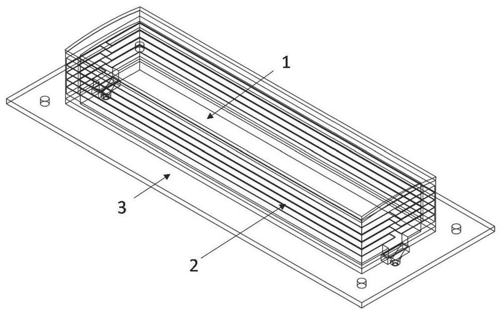
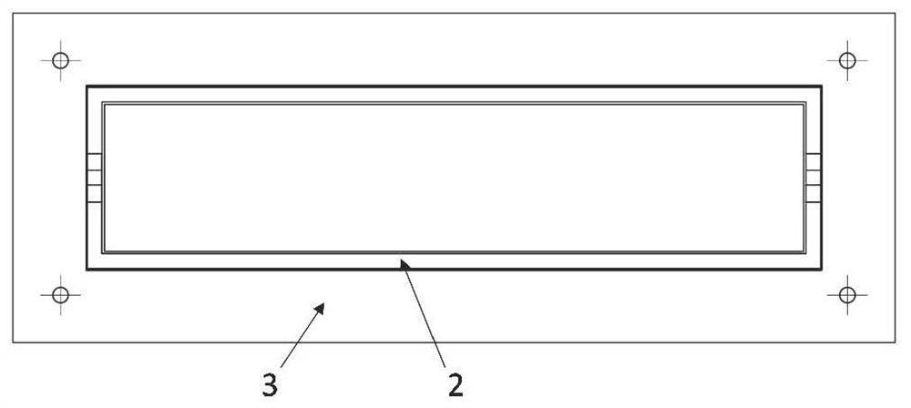
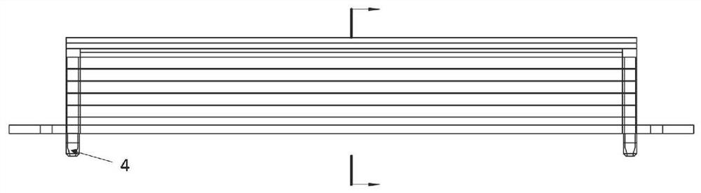
[0036] In an embodiment of the present invention, a bionic constant temperature antenna housing structure is provided, including an epidermis layer, a corium layer and a skeleton layer. The skin layer has the functions of bearing and heat insulation, and the service temperature of the skin layer is 100-2000°C. The epidermal layer includes an outer wall plate 1 and a wave-transmitting layer 5; the cortical layer includes a side wall plate 2 and a pipe joint 4; the skeleton layer is composed of a bottom plate 3, and its structure is as follows Figure 1 ~ Figure 2 shown.

[0037] The outer wall panel 1 is a thin-walled metal structure maintaining an aerodynamic shape, and the wave-transmitting layer 5 is a non-metallic thin-wall structure resistant to high temperature and wave-transmitting. The side wall panel 2 has a cavity structure, which ...


PUM

PropertyMeasurementUnit
Thicknessaaaaaaaaaa
Thicknessaaaaaaaaaa
Thicknessaaaaaaaaaa

Abstract

The invention provides a bionic constant-temperature antenna shell structure, which comprises an epidermal layer, a corium layer and a skeleton layer, wherein the epidermal layer comprises an outer wall plate (1) and a wave-transparent layer (5), the outer wall plate (1) is of a thin-wall metal structure for maintaining aerodynamic configuration, the wave-transparent layer (5) is of a high-temperature-resistant wave-transparent nonmetal thin-wall structure, the corium layer comprises a side wall plate (2), the side wall plate (2) is of a high-rigidity cavity structure, the side wall plate (2) is integrally formed in a hot blowing mode, the interior of the side wall plate (2) expands to form a cavity type structure imitating a biological circulation system, and is used for circulation of cooling liquid, the skeleton layer is composed of a bottom plate (3), the bottom plate (3) is of a light high-rigidity bionic sandwich structure, and the core part is a bionic sandwich layer and is of a bionic skeleton lattice structure or a porous structure of a bionic deep sea cavernous body or a honeycomb structure of a bionic honeycomb. According to the invention, a bionic structure type antenna shell structure integrated with various biological structure characteristics is developed, so that bearing / thermal control / loading multifunctional integration of a structure system is realized, and antenna structure weight reduction is realized.

Description

technical field [0001] The invention relates to an aircraft airborne antenna structure, which belongs to the technical field of aircraft structure design. Background technique [0002] As the speed of the aircraft increases, the aerodynamic heating of the outer surface of the aircraft becomes more and more significant, and a heat-resistant layer needs to be added to prevent heat from entering the aircraft. However, in order to ensure the wave-transmitting performance of the antenna on the outer surface of the aircraft, a heat-resistant layer cannot be added to the surface. Therefore, the design of the antenna shell needs to use high-temperature resistant materials, and the high temperature of the antenna cannot be conducted to the interior of the aircraft. The traditional antenna shell structure is no longer suitable for high-speed aircraft. It is necessary to design a new type of airborne antenna structure scheme to meet the urgent needs in the field of airborne antennas....

Claims


Application Information

Patent Timeline
IPC IPC(8): H01Q1/42H01Q1/02H01Q1/28
CPCH01Q1/42H01Q1/422H01Q1/28H01Q1/02
Inventor 王庆伟李晶冯蕾蕾吕文亮韩乐黄正石刘鹏
Owner BEIJING RES INST OF MECHANICAL & ELECTRICAL TECH
Why Eureka
Try Eureka