
Flue gas treatment system

A technology of flue gas treatment system and gas pipe, which is applied in the direction of gas treatment, air quality improvement, fixed duct assembly, etc., and can solve problems such as absorption of nitrogen oxide oxidation products, work influence, and insufficient flue gas treatment.

Inactive Publication Date: 2021-09-14
杭州同景科技有限公司
View PDF7 Cites 0 Cited by
  • Summary
  • Abstract
  • Description
  • Claims
  • Application Information

AI Technical Summary

Problems solved by technology

[0004] In order to overcome the incomplete treatment of the flue gas after dust removal in the prior art, the harmful elements in it still exist in the flue gas after treatment, which will affect the subsequent work; and due to the oxidation reaction in some washing tanks, if the smoke Insufficient oxidation of nitrogen oxides in the gas and insufficient absorption of oxidation products, the present invention provides a flue gas treatment system

Method used


Image

  • Flue gas treatment system
  • Flue gas treatment system
  • Flue gas treatment system

Examples


Embodiment Construction

[0028] In order to make the technical means, creative features, goals and effects achieved by the present invention easy to understand, the present invention will be further elaborated below in conjunction with specific embodiments, but the following embodiments are only preferred embodiments of the present invention, not all. Based on the examples in the implementation manners, other examples obtained by those skilled in the art without making creative efforts all belong to the protection scope of the present invention. The experimental methods in the following examples, unless otherwise specified, are conventional methods, and the materials, reagents, etc. used in the following examples, unless otherwise specified, can be obtained from commercial sources.

[0029] Example:

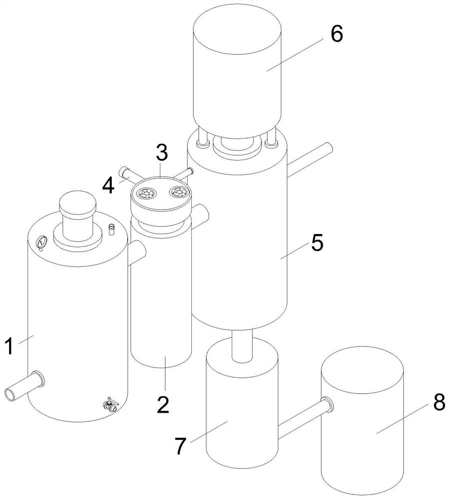
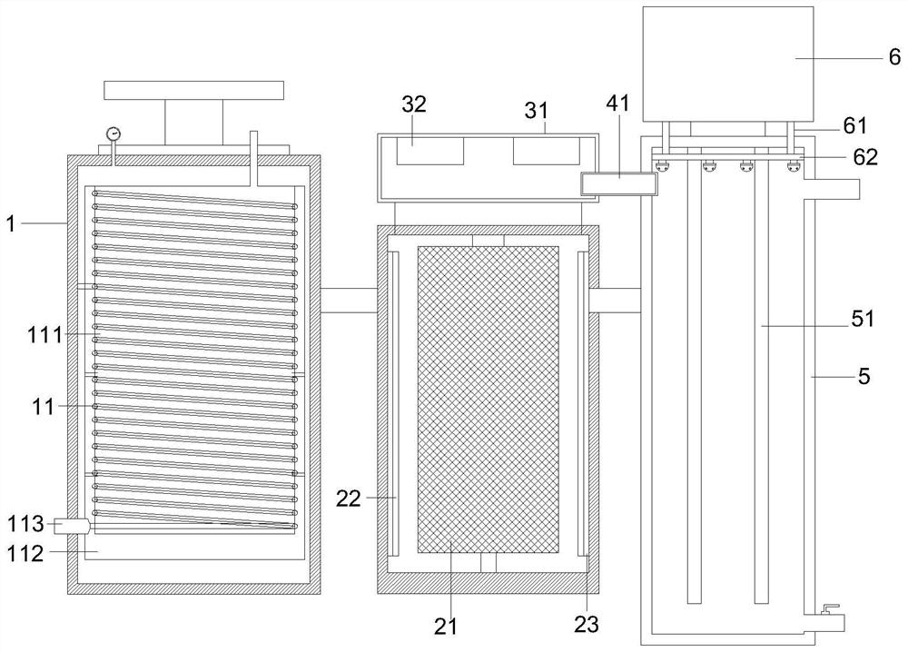
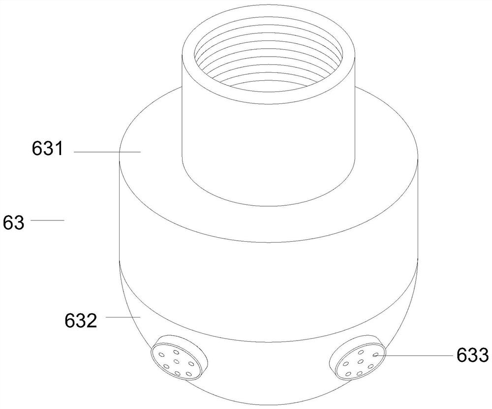
[0030] Such as Figure 1-5 As shown, the present invention provides a flue gas treatment system, including a reaction device 2 and a pressurization device 3, the reaction device 2 is arranged on the top...


PUM


Abstract

The invention discloses a flue gas treatment system which comprises a reaction device and a pressurizing device; the reaction device is arranged at the top end of the pressurizing device through a pipeline, the front end of the reaction device is communicated with a heat exchange device, one end of the pressurizing device is communicated with a washing tank, the top end of the washing tank is communicated with an ammonia water tank, and the bottom end of the washing tank is communicated with a compression device; one end of the compression device is communicated with a crystallizing tank; a structural carbon plate is arranged in the reaction device, the structural carbon plate is fixed in the reaction device through a mounting frame structure; heated liquid can be discharged through an inner cylinder for use for other purposes, and gas after heat exchange enters the reaction device for next operation, so that simpleness and convenience are achieved; the heat in the gas can be fully absorbed, energy waste is avoided, and oxidizing gas entering branch pipes reacts with sulfur-containing compounds in flue gas; and meanwhile, chemical adsorption is generated between the structural carbon plate and SO2, oxidation products of NO and HgO are adsorbed at the same time, and the purpose of removing pollutants is achieved.

Description

technical field [0001] The invention relates to the field of flue gas treatment systems, in particular to a flue gas treatment system. Background technique [0002] The combustion of fossil fuels produces a large amount of pollutants, including sulfur oxides, nitrogen oxides, etc., and their emissions have seriously exceeded the self-purification ability of the environment. The frequent smog weather in recent years is a warning to human beings. Therefore, it is necessary to control the pollutants produced by the combustion of fossil fuels. At present, the desulfurization technology for combustion equipment can be divided into three categories: dry method, semi-dry method and wet method. Among them, the dry and semi-dry methods have low investment and operation costs, but the desulfurization efficiency is not high. The flue gas generated by large-scale combustion equipment widely adopts efficient limestone / gypsum wet desulfurization technology (WFGD), which has high desulfur...

Claims


Application Information

Patent Timeline
IPC IPC(8): B01D53/78B01D53/76B01D53/60B01D53/50F28D1/047B01D53/32
CPCB01D53/60B01D53/78B01D53/76B01D53/50F28D1/047B01D53/32B01D2259/818B01D2251/2062Y02A50/20
Inventor 王超郭建萍严辉胡毕强钟伟伟
Owner 杭州同景科技有限公司
Learn More