
Wire drawing equipment with protection structure for steel wire production

A protective structure and steel wire technology, applied in metal processing equipment, manufacturing tools, metal processing, etc., can solve the problems of inconvenient multiple step-by-step drawing process, inconvenient external lubrication of steel wire, inconvenient collection of lubricating powder, etc.

Pending Publication Date: 2021-09-14
成都蒙德艾特自动化设备有限公司
View PDF0 Cites 1 Cited by
  • Summary
  • Abstract
  • Description
  • Claims
  • Application Information

AI Technical Summary

Problems solved by technology

[0004] The object of the present invention is to provide a wire drawing equipment with a protective structure for steel wire production, so as to solve the problem that the existing wire drawing equipment for steel wire production proposed in the background art is not convenient for one-time realization of multiple step-by-step steps during the wire drawing process. wire drawing process, and it is not convenient to uniformly lubricate the outside of the steel wire, and it is not convenient to collect the remaining lubricating powder

Method used

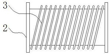

Image

  • Wire drawing equipment with protection structure for steel wire production
  • Wire drawing equipment with protection structure for steel wire production
  • Wire drawing equipment with protection structure for steel wire production

Examples


Embodiment Construction

[0026] The technical solutions in the embodiments of the present invention will be clearly and completely described below in conjunction with the accompanying drawings in the embodiments of the present invention. Obviously, the described embodiments are only some of the embodiments of the present invention, not all of them. Based on The embodiments of the present invention and all other embodiments obtained by persons of ordinary skill in the art without making creative efforts belong to the protection scope of the present invention.

[0027] In the description of the present invention, unless otherwise stated, the meaning of "plurality" is two or more; the terms "upper", "lower", "left", "right", "inner", "outer" , "front end", "rear end", "head", "tail", etc. indicate the orientation or positional relationship based on the orientation or positional relationship shown in the drawings, and are only for the convenience of describing the present invention and simplifying the desc...


PUM


Abstract

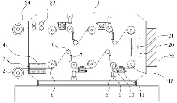
The invention discloses wire drawing equipment with a protection structure for steel wire production, and relates to the technical field of steel wire production. The wire drawing equipment comprises a machine frame, a lubricating mechanism and a display screen, wherein an unwinding drum is arranged on the lower left side of the exterior of the machine frame, a steel wire main body is arranged on the outer side of the unwinding drum, a water cooling box is fixed to the lower portion of the left side of the interior of the machine frame, the steel wire main body penetrates through a hollow groove inside the water cooling box, a first transition wheel, a guide wheel and a wire drawing die are sequentially arranged outside the steel wire main body from left to right, an electric push rod is arranged on the lower portion inside the machine frame, a support is fixed to the upper portion of the electric push rod, a tensioning wheel is arranged inside the support, and the tensioning wheel is located outside the steel wire main body. The wire drawing equipment has the beneficial effects that the first transition wheel, the guide wheel, the wire drawing die and the tensioning wheel inside the equipment is a one-time drawing process, and four-time drawing processes are arranged on the upper side and the lower side inside the machine frame in total so that the drawing precision can be effectively improved while the occupied area is saved.

Description

technical field [0001] The invention relates to the technical field of steel wire production, in particular to a wire drawing device with a protective structure for steel wire production. Background technique [0002] Steel wire is one of the four major types of steel plates, tubes, shapes, and wires. It is a reprocessed product made of hot-rolled wire rods by cold drawing. Wire drawing machine equipment, also known as metal wire drawing equipment, is based on the diameter of the wire drawing Roughly subdivided into: large drawing machine, medium drawing machine, small drawing machine, thin wire drawing machine, fine wire drawing machine, etc., which belong to the preprocessing equipment for the production of standard parts and other metal products, the purpose is to transport the steel produced by the steel manufacturer to the The wires or rods of standard parts and other metal products manufacturers are drawn by wire drawing machines, so that the diameter, roundness, inter...

Claims


Application Information

Patent Timeline
IPC IPC(8): B21C1/04B21C1/12B21C9/00B21C51/00
CPCB21C1/04B21C1/12B21C9/00B21C51/00
Inventor 葛珺彭辉邹色芳
Owner 成都蒙德艾特自动化设备有限公司
Learn More