
Yielding supporting structure

A supporting structure and pipe pressure technology, which can be applied to shaft lining, tunnel lining, underground chamber, etc., and can solve problems such as variable resistance

Pending Publication Date: 2021-09-14
CENT SOUTH UNIV
View PDF0 Cites 0 Cited by
  • Summary
  • Abstract
  • Description
  • Claims
  • Application Information

AI Technical Summary

Problems solved by technology

[0006] The purpose of the present invention is to provide a pressure-yielding support structure to solve the problem of variable resistance and pressure-yielding of the pressure-yielding support structure in stages

Method used


Image

  • Yielding supporting structure
  • Yielding supporting structure
  • Yielding supporting structure

Examples


Embodiment

[0037] see Figure 1 to Figure 9 , a pressure yielding support structure, this embodiment is applied to the self-adaptive variable resistance pressure yielding support of large deformation tunnels.

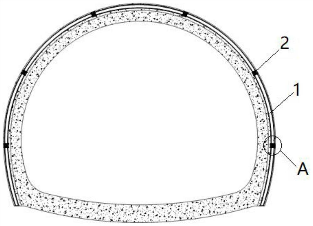
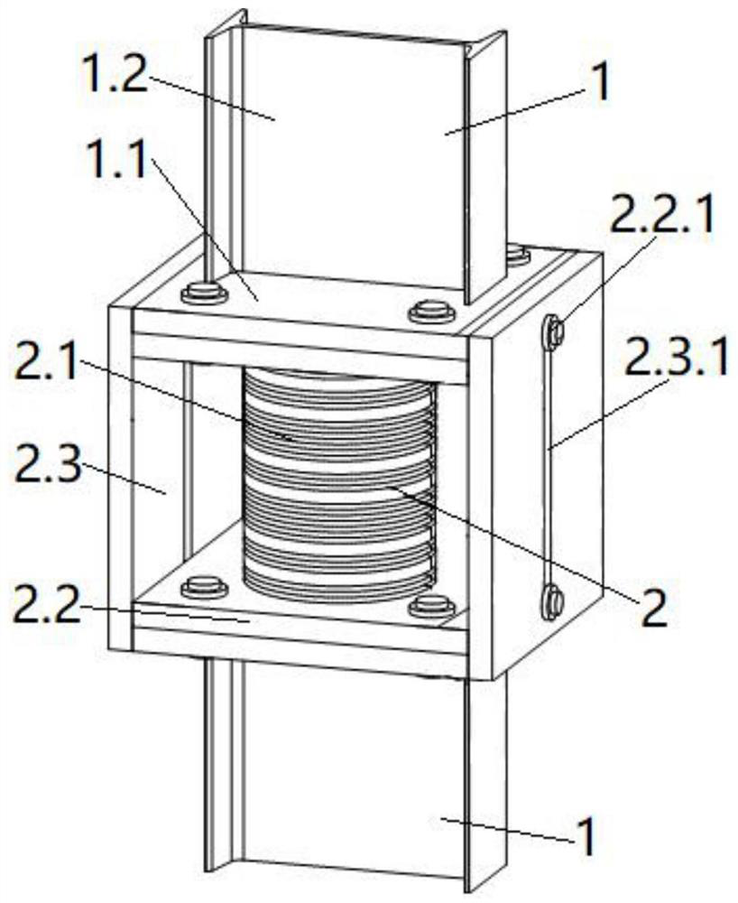
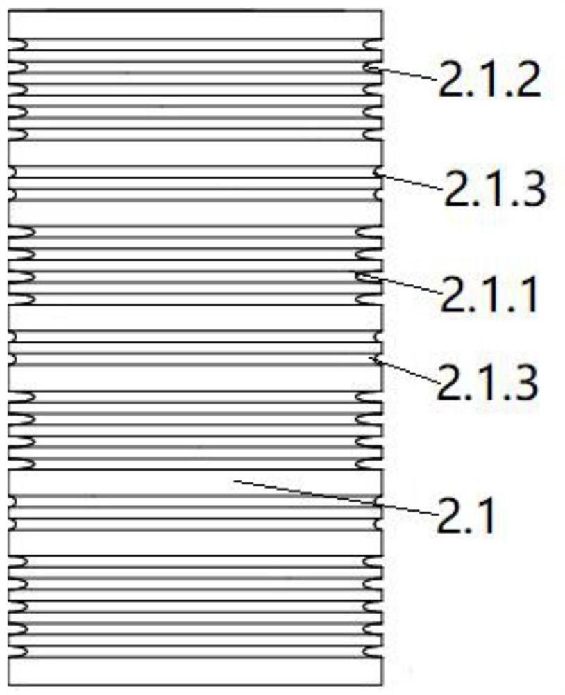
[0038] A pressure-yielding support structure, see figure 1 , including a plurality of arch units 1 and a plurality of pressure relief components 2; adjacent arch units 1 are connected by pressure relief components 2, and a plurality of arch units 1 are connected end to end to form an arc-shaped arch that matches the profile of the tunnel section ; see figure 2 with image 3, the pressure relief assembly 2 includes a pressure relief pipe 2.1, at least two dimpled areas with different concave depths are provided on the outer wall of the pressure relief pipe 2.1 along the axial direction of the pressure relief pipe 2.1; and the axis of the pressure relief pipe 2.1 The direction is parallel to the connection direction between the pressure relief assembly 2 and the arch unit 1 . ...


PUM

PropertyMeasurementUnit
Widthaaaaaaaaaa

Abstract

The invention provides a yielding supporting structure. The structure comprises a plurality of arch frame units and a plurality of yielding assemblies, wherein every two adjacent arch frame units are connected by means of the corresponding yielding assembly, the yielding assemblies comprise yielding pipes, and at least two corresponding concave grain areas with different concave depths are arranged on the outer wall of each yielding pipe in an axis direction of the yielding pipe. According to the structure, the at least two corresponding concave grain areas with the different concave depths are arranged on the outer wall of each yielding pipe in the axis direction of the yielding pipe, cross sectional areas of the concave grain areas of the yielding pipes are reduced by means of concave grains, and axial compressive rigidity of the concave grain areas of the yielding pipes is reduced, so that the yielding pipes are induced to generate axial compressive deformation in the concave grain areas when bearing surrounding rock pressure, and an active yielding effect is achieved; and the higher cutting depths of the concave grains are, the lower the compressive rigidity of the whole structure is, and by arranging the at least two corresponding concave grain areas with the different concave depths on the outer wall of each yielding pipe, a staged resistance changing effect can be achieved according to change of surrounding rock pressure borne by the yielding supporting structure.

Description

technical field [0001] The invention relates to the technical field of tunnel engineering, in particular to a yielding support structure. Background technique [0002] In recent years, with the continuous advancement of my country's western development strategy, a large number of deep and long tunnel projects passing through high ground stress areas and weak surrounding rock formations have emerged, such as the Sichuan-Tibet Railway and the Yunnan-Tibet Railway under construction. Affected by complex geological conditions and tectonic stress, large deformation problems in soft rock characterized by fast deformation rate, large deformation magnitude, and long convergence duration are prone to occur during tunnel construction. In view of the large deformation of tunnels, the support technologies adopted at home and abroad can be divided into three categories: strong support, layered support and yield support. Among them, the pressure-yielding support technology is to properly...

Claims


Application Information

Patent Timeline
IPC IPC(8): E21D11/18B23P15/00
CPCE21D11/183B23P15/00
Inventor 雷明锋朱彬彬贾朝军赵晨阳黄娟施成华郑可跃龚琛杰
Owner CENT SOUTH UNIV
Learn More