
Clamping control system and method for lagging jack mounting trolley

An arch installation and control system technology, which is applied to fluid pressure actuation system components, shaft equipment, earthwork drilling and production, etc., and can solve problems such as long cycle, device vibration, and high cost

Pending Publication Date: 2021-09-14
CHENGDU XINZHU CONCRETE MASCH EQUIP CO LTD
View PDF0 Cites 0 Cited by
  • Summary
  • Abstract
  • Description
  • Claims
  • Application Information

AI Technical Summary

Problems solved by technology

[0005] Hydraulic motors and hydraulic pumps will inevitably wear out after long-term operation, resulting in looseness and gaps in the components of the hydraulic device, causing the device to vibrate and further generating noise
The traditional method to reduce or eliminate the noise of hydraulic motors and hydraulic pumps is to replace better hydraulic pumps and optimize hydraulic pipelines. This traditional method is costly and takes a long time

Method used


Image

  • Clamping control system and method for lagging jack mounting trolley
  • Clamping control system and method for lagging jack mounting trolley

Examples


Embodiment 1

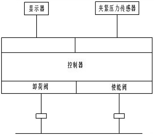
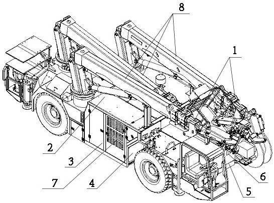
[0027] An arch installation trolley clamping control system, including a trolley, the actuator 7 of the trolley is provided with an actuator enabling valve 2 and an actuator unloading valve 4, and the actuator enabling valve 2 and The actuator unloading valves 4 are all connected with the controller 5; the arm frame 8 of the trolley is provided with a clamping device 1, and the clamping device 1 is connected with the clamping pressure sensor 3, and the clamping pressure The sensor 3 is also connected with the controller 5; a display 6 is arranged in the operating room of the trolley, and the display 6 is connected with the controller 5, and the controller 5 is arranged in the electric control cabinet of the trolley where the arch is installed .

[0028] Further, in this embodiment, the clamping pressure sensor 3 is used to detect the real-time clamping pressure of the clamping device 1 on the arm frame 8 of the trolley on which the arch is installed.

[0029] Further, in this...

Embodiment 2

[0045] In order to ensure the transmission efficiency of data, in this embodiment: a trolley clamping control system for arch installation, including a trolley, the actuator 7 of the trolley is provided with an actuator enabling valve 2 and an actuator The unloading valve 4, the actuator enable valve 2 and the actuator unloading valve 4 are all connected to the controller 5; the arm frame 8 of the trolley is provided with a clamping device 1, and the clamping device 1 It is connected with the clamping pressure sensor 3, and the clamping pressure sensor 3 is also connected with the controller 5; a display 6 is arranged in the operating room of the trolley, and the display 6 is connected with the controller 5, and the control The device 5 is arranged in the electric control cabinet of the arch frame installation trolley.

[0046] Further, in this embodiment, the clamping pressure sensor 3 is used to detect the real-time clamping pressure of the clamping device 1 on the arm frame...


PUM


Abstract

The invention discloses a clamping control system and method for a lagging jack mounting trolley. The system comprises the trolley, an actuating mechanism enabling valve (2) and an actuating mechanism unloading valve (4) are arranged on an actuating mechanism (7) of the trolley, and the actuating mechanism enabling valve (2) and the actuating mechanism unloading valve (4) are both connected with a controller (5); a clamping device (1) is arranged on an arm support (8) of the trolley, the clamping device (1) is connected with a clamping pressure sensor (3), and the clamping pressure sensor (3) is further connected with the controller (5); and a display (6) is arranged in an operation room of the trolley and is connected with the controller (5). Noise of a hydraulic system of the trolley during working can be greatly reduced, and thus a comfortable operation environment is provided for an operator.

Description

technical field [0001] The invention relates to the technical field of engineering machinery, in particular to a clamping control system and method for an arch mounting trolley. Background technique [0002] At present, my country's highway tunnels, railway tunnels and soft rock tunnels are still in the early stage of tunnel construction mechanization, and the overall technology is still lagging behind developed countries. The mechanized rapid construction technology system based on the drill-and-blast method has not yet been completed, and the key technical problems in supporting equipment have not yet been broken through. The construction progress varies greatly, and there are many hidden dangers of accidents during the construction process. The main construction equipment on its operation line is mostly imported from abroad, and the self-developed varieties are relatively small, with poor quality and high failure rate, and the main technical performance parameters do not ...

Claims


Application Information

Patent Timeline
IPC IPC(8): F15B21/02F15B21/00F15B13/02E21D11/18E21D11/40
CPCF15B21/02F15B21/008F15B21/085F15B13/02E21D11/18E21D11/40F15B2211/6306F15B2211/6656F15B2211/8616
Inventor 毛闻雯张林
Owner CHENGDU XINZHU CONCRETE MASCH EQUIP CO LTD
Learn More