Micro-flow pump control valve device testing system and testing method

A test system and micro-flow technology, applied in the testing of machine/structural components, mechanical valve testing, fluid tightness testing, etc., can solve problems such as micro-flow control pump valve testing

Pending Publication Date: 2021-09-14
SUZHOU IN SITU CHIP TECH CO LTD
View PDF0 Cites 1 Cited by
  • Summary
  • Abstract
  • Description
  • Claims
  • Application Information

AI Technical Summary

Problems solved by technology

[0007] The purpose of the present invention is to provide a micro-flow control pump valve dev

Method used


Image

  • Micro-flow pump control valve device testing system and testing method
  • Micro-flow pump control valve device testing system and testing method
  • Micro-flow pump control valve device testing system and testing method

Examples


Embodiment 1

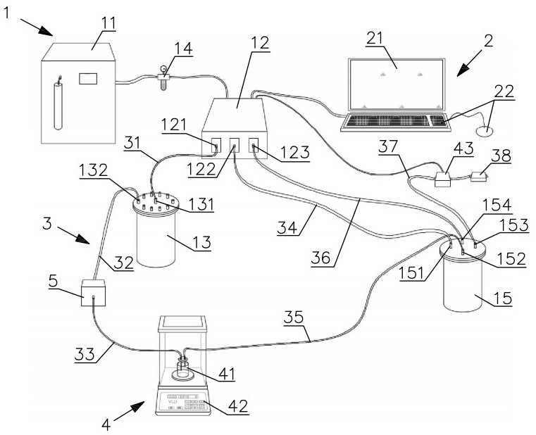
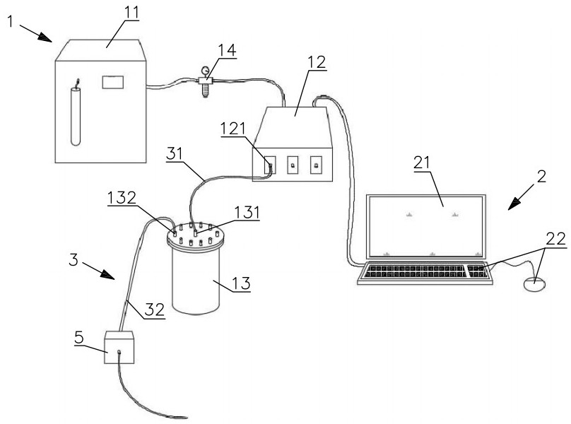
[0064] Such as figure 1 , the testing system includes a pressure control component 1 , a display operation component 2 , a pipeline wiring component 3 and a metering component 4 .

[0065] The pressure control assembly 1 includes an air compressor 11 , a pressure controller 12 , a liquid pressure tank 13 , an air-hydraulic pressure tank 15 and an air filter 14 . The air filter 14 is connected between the air compressor 11 and the pressure controller 12 . The pressure controller 12 is connected to the air compressor 11 through its gas inlet, and the pressure controller 12 has three gas outlets 121 , 122 , 123 . The gas outlet 121 is connected to the air inlet 131 of the liquid pressure tank 13 . The gas outlets 122 and 123 are respectively connected to the air inlets 151 and 154 of the gas-liquid pressure tank 15 .

[0066] Such as Figure 7 , The liquid pressure tank 13 has an air inlet 131 and a liquid outlet 132 . Wherein, there are multiple liquid outlets 132 . When t...

Embodiment 2

[0107] Such as Figure 9 The illustrated embodiment 2 is based on the embodiment 1 and extended to a batch test, which can simultaneously detect multiple micro-flow control pump valve devices 5, thereby improving the detection efficiency.

[0108] In this embodiment, there are multiple double-port sealed weighing bottles 41 and precision balances 42 . Multiple liquid outlets 132 on the liquid pressure tank 13 are connected to different micro-flow control pump valve devices 5 , and the liquid outlets of the micro-flow control pump valve devices 5 are connected to the left port of the corresponding double-port sealed weighing bottle 41 . The right ports of multiple double-port sealed weighing bottles 41 are merged and connected to the gas outlet 152 so as to be indirectly connected to the gas outlet 122 of the pressure controller 12 . The right ports of the plurality of double-port sealed weighing bottles 41 can also be directly connected to the gas outlet 122 of the pressure c...


PUM


Abstract

The invention relates to a micro-flow pump control valve device testing system and method. A micro-flow pump control valve device is used for pumping low-flow liquid and is provided with a liquid inlet and a liquid outlet. The testing system comprises a pressure control assembly which comprises an air compressor, a pressure controller, a liquid pressure tank and a gas-liquid pressure tank; a display operation assembly which is electrically connected with the signal input port of the pressure controller, and comprises a display and an instruction input mechanism; and a metering assembly which comprises a precise weighing machine, a double-interface sealed weighing bottle and a pressure sensor. One interface of the double-interface sealed weighing bottle is in pluggable connection with a liquid outlet of the micro-flow pump control valve device through a pipeline, and the other interface of the double-interface sealed weighing bottle is in direct or indirect pipeline connection with a gas outlet of the pressure controller. The pressure sensor is selectively arranged on a liquid discharging pipeline of the micro-flow pump control valve device, and the signal output end of the pressure sensor is directly or indirectly electrically connected with the display operation assembly. Multiple indexes of the micro-flow pump control valve device can be tested.

Description

technical field [0001] The invention relates to a micro-flow control pump valve device testing system, which is used for accurately testing the micro-flow control pump valve device, and also relates to a test method using the test system. Background technique [0002] Accurate monitoring and control of liquid flow at low flow rates is becoming increasingly important in contemporary biomedical research and industrial monitoring. Especially for drug delivery devices, such as various medical infusion pumps, implantable drug delivery devices, microdialysis tubes and other microfluidic devices, the accuracy of delivery is a prerequisite for safety assurance. The pumps and valves in microfluidic devices are usually simple in structure, but the movement of the conveying and controlling medium in the pumps and valves is very complicated. At present, there is no general physical model and analytical method that can accurately determine the pumps and valves under different working con...

Claims


Application Information

Patent Timeline
IPC IPC(8): G01M13/003G01L11/00G01M3/28
CPCG01M13/003G01L11/00G01M3/2876
Inventor 马硕
Owner SUZHOU IN SITU CHIP TECH CO LTD
Why Eureka
Try Eureka