Conveyor carrier roller friction wear test bench
A friction and wear, conveyor technology, applied in the direction of testing wear resistance, measuring devices, using mechanical devices, etc., can solve the problem of difficulty in measuring the friction coefficient of idlers
- Summary
- Abstract
- Description
- Claims
- Application Information
AI Technical Summary
Problems solved by technology
Method used
Image
Examples
Embodiment 1
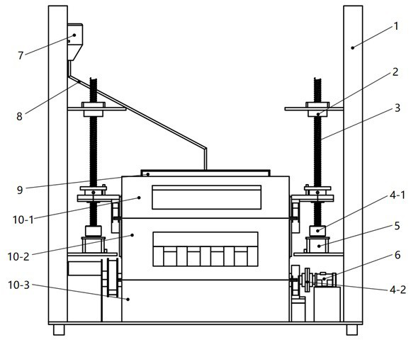
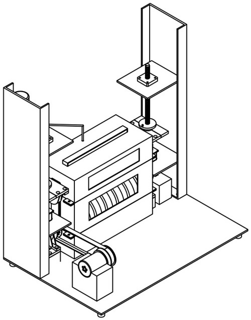
[0041] First install the rubberized drum 18 into the lower environment chamber 10-3, start the machine now, the driving motor drives the rubberized drum to run idly, and record the torque at this moment by the torque sensor M 1 . Then stop the machine and install the tested test idler roller 17 in the environment chamber 10-2 after weighing, put the dust of the simulated environment in the dust box 9-1 after covering the upper environment chamber, and place the liquid of the required simulated environment Loaded into the atomizer 7, the preparation required for the test is over.
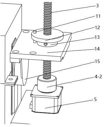
[0042] Further, the loading motor 5 is turned on to apply pressure to the test roller 17 so that the test roller 17 is in close contact with the rubber drum 18 and there is a certain positive pressure. The positive pressure applied by the loading motor 5 can be recorded by the computer or the display device. The values of the side ring pressure sensors are F 1 、F 2 .
[0043] Further open th...
Embodiment 2
[0047] The method for carrying out the wear test of the idler roller on the conveyor idler roller friction and wear test bench is characterized in that it comprises the following steps:
[0048] Step 1: Before the test starts, the radius of the lagging roller can be known—— r
[0049] Step 2: Weigh the test roller before the start of the test to obtain the quality of the test roller—— m
[0050]Step 3: Start the machine and get the no-load torque from the torque sensor under the condition of no load—— M 1
[0051] Step 4: Apply load to the test idler roller through the loading part, and obtain the positive pressure between the test idler roller and the rubberized roller from the ring pressure sensors on the left and right sides of the loading screw—— F 1 、F 2
[0052] Step 5: Start up and get the under-load torque from the torque sensor under loading conditions—— M 2
[0053] The coefficient of friction is calculated as follows:
[0054]
[0055] in
[0056] ...
PUM
 Abstract
Description
Claims
Application Information
 - R&D
- Intellectual Property
- Life Sciences
- Materials
- Tech Scout
- Unparalleled Data Quality
- Higher Quality Content
- 60% Fewer Hallucinations
Browse by: Latest US Patents, China's latest patents, Technical Efficacy Thesaurus, Application Domain, Technology Topic, Popular Technical Reports.
© 2025 PatSnap. All rights reserved.Legal|Privacy policy|Modern Slavery Act Transparency Statement|Sitemap|About US| Contact US: help@patsnap.com


