Low-profile dual-band wave-absorbing surface applied to vehicle-mounted radar test environment and manufacturing method of low-profile dual-band wave-absorbing surface

A test environment, vehicle radar technology, applied in the direction of antenna, electrical components, etc., can solve the problem of the high profile of the pyramid absorbing material

Active Publication Date: 2021-09-14
YANGTZE DELTA REGION INST OF UNIV OF ELECTRONICS SCI & TECH OF CHINE HUZHOU
View PDF16 Cites 2 Cited by
  • Summary
  • Abstract
  • Description
  • Claims
  • Application Information

AI Technical Summary

Problems solved by technology

[0006] The purpose of the present invention is to overcome the deficiencies in the prior art above, to provide a low-profile dual-band wave-absorbing surface applied to the vehicle-mounted radar testing environment and its manufacturing method, in order to ensure that the wave-absorbing material can absorb 24GHz and 77GHz dual-vehicle radar frequency bands At the same time as stray electromagnetic waves, it solves the problems that the profile of the traditional pyramid absorbing material is too high and the existing flat absorber can only support the frequency band of a single vehicle radar

Method used


Image

  • Low-profile dual-band wave-absorbing surface applied to vehicle-mounted radar test environment and manufacturing method of low-profile dual-band wave-absorbing surface
  • Low-profile dual-band wave-absorbing surface applied to vehicle-mounted radar test environment and manufacturing method of low-profile dual-band wave-absorbing surface
  • Low-profile dual-band wave-absorbing surface applied to vehicle-mounted radar test environment and manufacturing method of low-profile dual-band wave-absorbing surface

Examples


Embodiment Construction

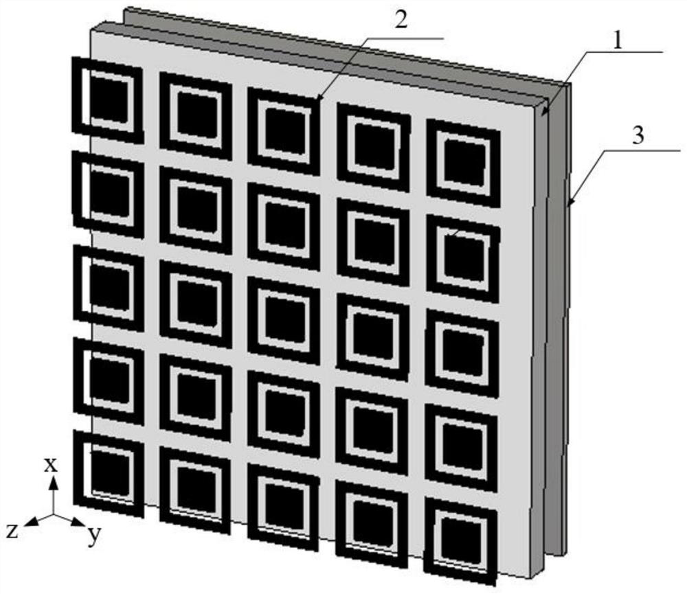
[0033] The overall structure of a low-profile dual-band wave-absorbing surface applied to the vehicle radar test environment is as follows: figure 1 As shown, it includes a dielectric substrate 1 , a two-dimensional planar periodic array 2 printed on the front of the dielectric substrate 1 , and a metal floor 3 printed on the back of the dielectric substrate. The overall structure from top to bottom is a two-dimensional planar periodic array 2, a dielectric substrate 1, and a metal floor 3.

[0034] The two-dimensional planar periodic array 2 is formed by periodic arrangement of resistive frequency selective units along two directions of the x-axis and the y-axis.

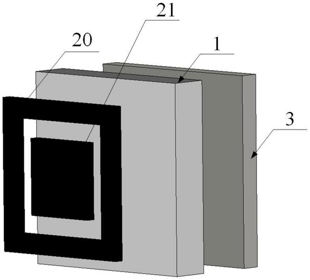
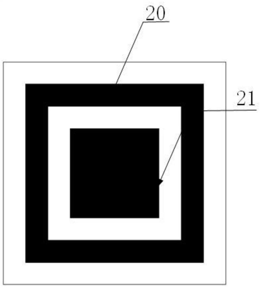
[0035] Such as figure 2 , 3 , 4, the resistive frequency selective unit of the two-dimensional planar periodic array 2 is a planar nesting structure composed of a square ring 20 and a square patch 21, the square ring 20 and the square patch 21 are concentric, and the square The side length of the patch 21 is le...


PUM

PropertyMeasurementUnit
thicknessaaaaaaaaaa
widthaaaaaaaaaa
widthaaaaaaaaaa

Abstract

The invention discloses a low-profile dual-band wave-absorbing surface applied to a vehicle-mounted radar test environment. The low-profile dual-band wave-absorbing surface comprises a dielectric substrate, an array printed on the front surface of the dielectric substrate and formed by periodically arranging resistive frequency selection units, and a metal floor printed on the back surface of the dielectric substrate, and the resistive frequency selection unit is composed of a resistive square ring and a resistive square patch, and the square patch is embedded in a hollow area of the square ring. According to the invention, effective absorption of electromagnetic waves can be realized in two vehicle-mounted radar frequency bands of 24GHz and 77GHz for omnidirectional angles, pitch angles within 30 degrees, TE polarized incident waves and TM polarized incident waves. Compared with the prior art, the low-profile dual-band wave-absorbing surface has the advantages of extremely low profile, light weight and simplicity and convenience in processing and mounting, can effectively eliminate the interference of stray electromagnetic waves when being applied to a vehicle-mounted radar test environment, can greatly reduce the occupied space of a test system, and has a very good engineering application prospect.

Description

technical field [0001] The invention belongs to the technical field of vehicle-mounted radar, and relates to a low-profile dual-band wave-absorbing surface applied to a vehicle-mounted radar testing environment and a manufacturing method thereof. Background technique [0002] When testing the radio frequency performance of vehicle-mounted radar in the industry, it is often necessary to place the vehicle-mounted radar in a microwave shielding box, or place a real or model car equipped with a vehicle-mounted radar in an open field or tunnel that simulates the actual driving environment of the vehicle. The microwave shielding box is a metal box with electromagnetic shielding function, and its inner surface needs to be equipped with wave-absorbing materials to absorb various stray electromagnetic waves to eliminate its interference to the test. And the open test site or the inner wall of the tunnel also needs to be pasted with wave-absorbing materials to absorb various stray int...

Claims


Application Information

Patent Timeline
Patent Type & Authority Applications(China)
IPC IPC(8): H01Q17/00
CPCH01Q17/008
Inventor 杨歆汨张颖黄晨路万家辉陈志
Owner YANGTZE DELTA REGION INST OF UNIV OF ELECTRONICS SCI & TECH OF CHINE HUZHOU
Why Eureka
Try Eureka