
Steel-concrete-wood combined beam

A technology of composite beams and wooden beams, applied in the direction of joists, girders, truss beams, etc., can solve the problems that the flammability of wood is easily affected by adverse environments, there are many construction procedures for on-site pouring, and the steel structure is heat-resistant and not fire-resistant. The prefabrication process is simple and easy, the economic benefits are outstanding, and the effect of good bearing effect

Active Publication Date: 2021-09-17
XIJING UNIV
View PDF7 Cites 0 Cited by
  • Summary
  • Abstract
  • Description
  • Claims
  • Application Information

AI Technical Summary

Problems solved by technology

[0003] However, the steel structure has the disadvantages of heat and fire resistance, easy to rust, and poor corrosion resistance; the concrete structure has the disadvantages of self-heavy, poor crack resistance, many on-site pouring construction procedures, and is limited by the construction environment and climatic conditions; the timber used in the wooden structure It has bad defects such as flammability and vulnerability to adverse environments
The performance defects of the materials used in the above structures restrict the size of the components and limit the application range of the components

Method used


Image

  • Steel-concrete-wood combined beam
  • Steel-concrete-wood combined beam
  • Steel-concrete-wood combined beam

Examples


Embodiment Construction

[0024] The present invention will be further described below in conjunction with the accompanying drawings.

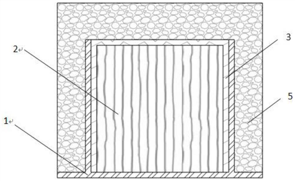
[0025] see figure 1 , a steel-concrete-wood composite beam, comprising an inverted Π-shaped steel 1, a wooden beam 2 is arranged inside the inverted Π-shaped steel 1, a thin-walled profiled steel plate 3 is arranged between the wooden beam 2 and the inverted Π-shaped steel 1, and the concrete 5 pouring on the outside of inverted Π-shaped steel 1, wooden beam 2 and thin-walled profiled steel plate 3.

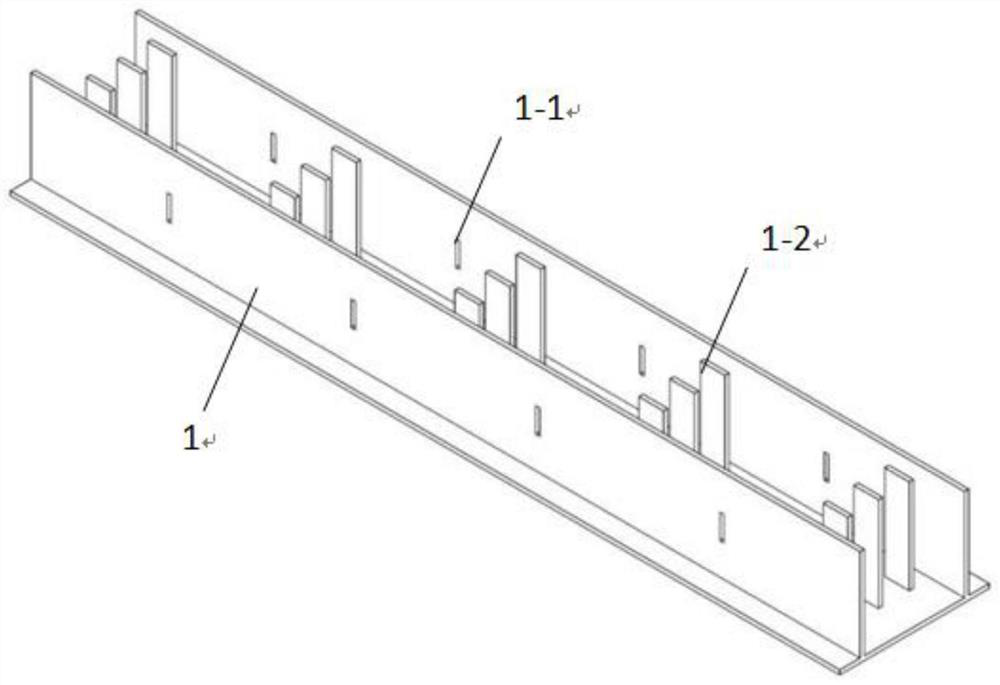
[0026] see figure 2 , the inner bottom wall of the inverted Π-shaped steel 1 is equidistantly provided with anchor pile groups 1-2, and the first nail insertion holes are arranged symmetrically between adjacent anchor pile groups 1-2 and on the flange plates on both sides of the inverted Π-shaped steel 1 1-1.

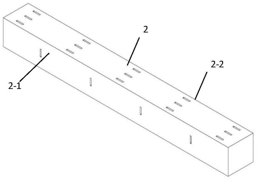
[0027] see image 3 , the wooden beam 2 is longitudinally provided with an anchor pile hole 2-2, and the anchor pile hole 2-2 is adapted to be connected with ...


PUM


Abstract

The invention provides a steel-concrete-wood combined beam. The steel-concrete-wood combined beam comprises inverted n-shaped steel, anchoring pile groups are arranged on the inner bottom wall of the inverted n-shaped steel at equal intervals, and first inserting nail holes are symmetrically formed in the positions, between the adjacent anchoring pile groups, of flange plates on the two sides of the inverted n-shaped steel; a wood beam is connected with the anchoring pile groups of the inverted n-shaped steel in a matched mode through anchoring pile holes, a thin-wall profiled steel sheet is arranged between the wood beam and the inverted n-shaped steel, the wood beam, the thin-wall profiled steel sheet and the inverted n-shaped steel are horizontally provided with the first inserting nail holes, second inserting nail holes and third inserting nail holes which are communicated with one another, the inverted n-shaped steel, the wood beam and the thin-wall profiled steel sheet are connected into a whole through inserting nails inserted into the first inserting nail holes, the second inserting nail holes and the third inserting nail holes, and concrete is poured on the periphery. According to the steel-concrete-wood combined beam, application of steel, the concrete and wood is combined with an assembly type beam structure, the excellent performance of the steel, the excellent performance of the concrete and the excellent performance of the wood are fully utilized, splicing connection is rapid and stable, the beam is integrated by pouring the concrete on a construction site, and good integrity is achieved; the prefabrication process is simple, convenient and easy to implement, a large amount of manpower and material resources are saved, the use amount of the concrete is reduced, the self weight of the beam is reduced, the economic benefits are outstanding, and the practicability and the feasibility are high.

Description

technical field [0001] The invention belongs to the technical field of civil engineering structures, in particular to a steel-concrete-wood composite beam. Background technique [0002] As the most representative structural forms today, steel, concrete, wood structures and their corresponding composite structures are widely used in various construction projects such as houses, bridges, roads, and dams. The advantages of its steel structure are uniform material, high strength, good toughness and plasticity, and industrial production; the advantages of concrete structure are good moldability, reasonable strength-to-price ratio, good durability, and integrally poured reinforced concrete structure. etc.; wooden structure has the characteristics of light weight, high strength, good seismic performance, high assembly level, and conforms to the green and energy-saving architectural concept. Steel, concrete, and wood structures are used in different fields due to their own advantag...

Claims


Application Information

Patent Timeline
Patent Type & Authority Applications(China)
IPC IPC(8): E04C3/29E01D19/00
CPCE04C3/29E01D19/00
Inventor 高山周林强张开元
Owner XIJING UNIV
Learn More