Phase synchronization method, spaceborne radar and ground receiving station

A spaceborne radar and ground technology, applied in the phase synchronization method, spaceborne radar and ground receiving station field, can solve the problem of reducing the accuracy of functional measurement

Pending Publication Date: 2021-09-17
AEROSPACE INFORMATION RES INST CAS
View PDF0 Cites 0 Cited by
  • Summary
  • Abstract
  • Description
  • Claims
  • Application Information

AI Technical Summary

Problems solved by technology

[0002] In a distributed satellite radar system, since the radars on different satellites use different frequency sources, there must be a fixed frequency difference between the radar carriers and a time-varying frequency difference caused by phase noise. Therefore, when using a distributed satellite radar system When using the interferometric altimetry function or the ground moving target detection function, the existence of these fixed frequency differences and time-varying frequency differences will reduce the measurement accuracy of these functions

Method used


Image

  • Phase synchronization method, spaceborne radar and ground receiving station
  • Phase synchronization method, spaceborne radar and ground receiving station
  • Phase synchronization method, spaceborne radar and ground receiving station

Examples


Embodiment 1

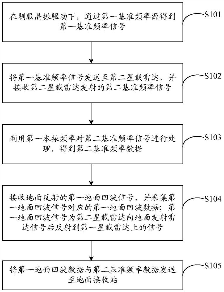
[0089] The embodiment of the present application provides a phase synchronization method, which is applied to the first spaceborne radar, figure 1 The flow of a phase synchronization method provided in the embodiment of the present application Figure 1 ,like figure 1 As shown, the phase synchronization method may include:

[0090] S101. Under the driving of a taming crystal oscillator, obtain a first reference frequency signal through a first reference frequency source.

[0091] In the embodiment of the present application, the first spaceborne radar obtains the first reference frequency signal through the first reference frequency source under the driving of the taming crystal oscillator.

[0092] It should be noted that the first reference frequency source is one of the components of the first spaceborne radar, and is responsible for generating various reference frequencies required by the first spaceborne radar.

[0093] It should be noted that, after the first referenc...

Embodiment 2

[0202] Based on the same inventive concept of the first embodiment, the embodiment of the present application provides a first spaceborne radar 1, which corresponds to a phase synchronization method applied to the first spaceborne radar; Figure 9 Schematic diagram of the composition and structure of a first spaceborne radar provided in the embodiment of the present application Figure 1 ,like Figure 9 As shown, the first spaceborne radar 1 may include:

[0203] The sending module 11 is used to obtain a first reference frequency signal through the first reference frequency source under the drive of the taming crystal oscillator, and send the first reference frequency signal to the second spaceborne radar for the second spaceborne radar Using the second crystal oscillator frequency corresponding to the second spaceborne radar to process the first reference frequency signal to obtain first reference frequency data;

[0204] a receiving module 12, configured to receive the sec...


PUM


Abstract

The embodiment of the invention provides a signal synchronization method, a spaceborne radar and a ground receiving station, and is applied to a first spaceborne radar, and the method comprises the steps: obtaining a first reference frequency signal through a first reference frequency source under the drive of a taming crystal oscillator; sending the first reference frequency signal to a second spaceborne radar, and receiving a second reference frequency signal transmitted by the second spaceborne radar; processing the second reference frequency signal by using the first local frequency to obtain second reference frequency data; receiving a first ground echo signal reflected by the ground, and collecting first ground echo data corresponding to the first ground echo signal, wherein the first ground echo signal is a signal reflected to the first spaceborne radar after the second spaceborne radar transmits a radar signal to the ground; and sending the first ground echo data and the second reference frequency data to a ground receiving station.

Description

technical field [0001] The present application relates to the technical field of spaceborne radar, and in particular, to a phase synchronization method, spaceborne radar and ground receiving station. Background technique [0002] In a distributed satellite radar system, since the radars on different satellites use different frequency sources, there must be a fixed frequency difference and a time-varying frequency difference caused by phase noise between the radar carriers. When the interferometric altimetry function or the ground moving target detection function is used, the existence of these fixed frequency differences and time-varying frequency differences will reduce the measurement accuracy of these functions. SUMMARY OF THE INVENTION [0003] The embodiments of the present application provide a phase synchronization method, a spaceborne radar, and a ground receiving station, which can eliminate the fixed frequency difference and the time-varying frequency difference ...

Claims


Application Information

Patent Timeline
IPC IPC(8): G01S13/87G01S7/42G01S7/40
CPCG01S13/87G01S7/42G01S7/40Y02A90/10
Inventor 李世强禹卫东岳海霞
Owner AEROSPACE INFORMATION RES INST CAS
Why Eureka
Try Eureka