Eureka AIR delivers breakthrough ideas for toughest innovation challenges, trusted by R&D personnel around the world.

High-precision optical fiber time transfer system and method

A time-transfer, high-precision technology, applied in optical fiber transmission, time-division multiplexing systems, electrical components, etc., can solve problems that have not yet collected data, found no explanations or reports, etc., and achieve simple and efficient calibration and generation schemes. Wide applicability and effect of improving transfer accuracy

Active Publication Date: 2020-05-05
SHANGHAI INST OF OPTICS & FINE MECHANICS CHINESE ACAD OF SCI
View PDF5 Cites 0 Cited by
  • Summary
  • Abstract
  • Description
  • Claims
  • Application Information

AI Technical Summary

Problems solved by technology

However, the same as the existing technology 3, since the time signal transmission also adopts the technical scheme of direct level modulation and direct detection of optical power, the bandwidth of the optoelectronic device and the rising edge of the time pulse are still the key factors restricting the performance of time transmission
[0008] At present, there is no description or report of similar technology to the present invention, and no similar information has been collected at home and abroad

Method used

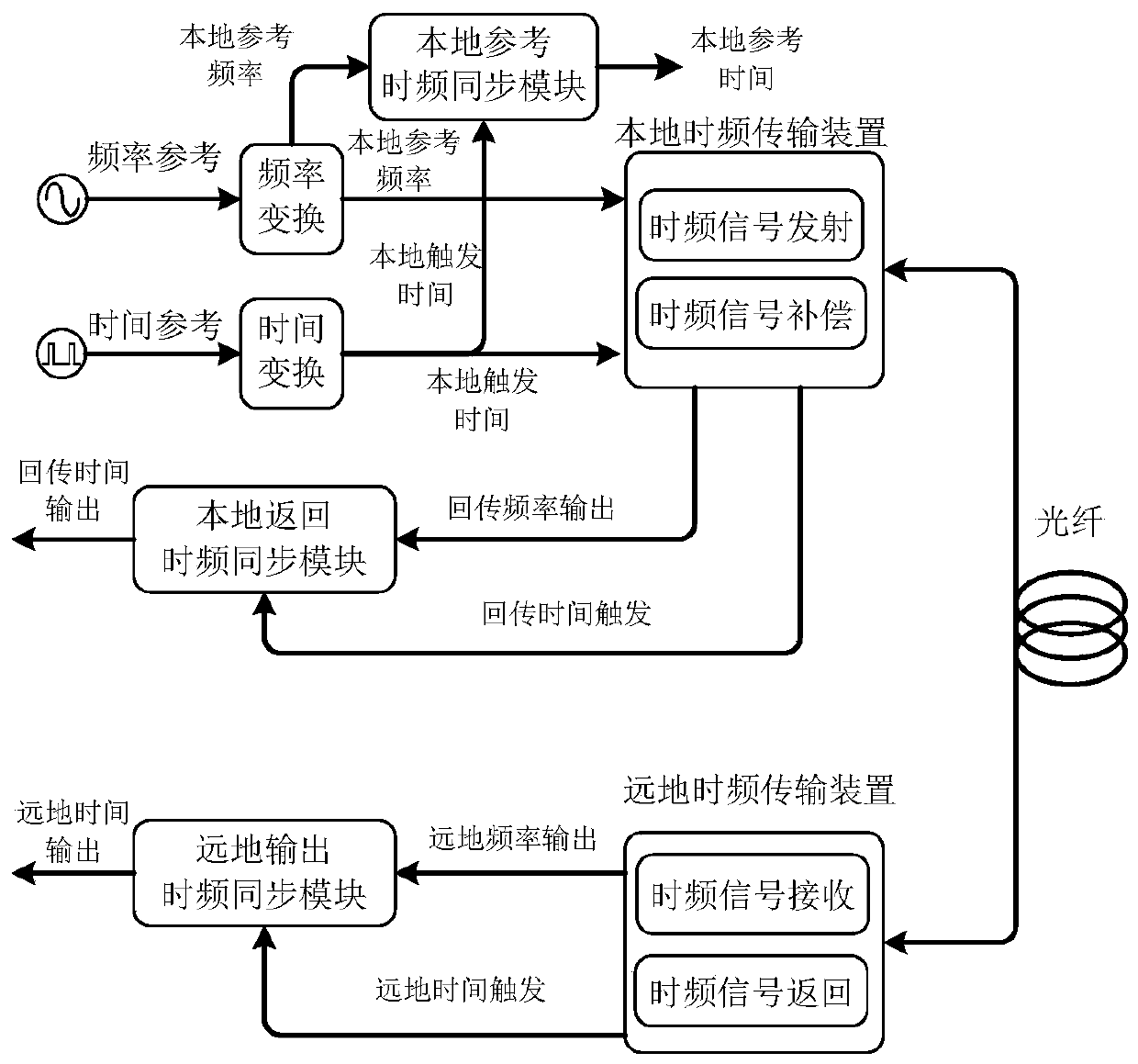

Image

  • High-precision optical fiber time transfer system and method
  • High-precision optical fiber time transfer system and method
  • High-precision optical fiber time transfer system and method

Examples


Embodiment Construction

[0047] The following is a detailed description of the embodiments of the present invention: this embodiment is implemented on the premise of the technical solution of the present invention, and provides detailed implementation methods and specific operation processes. It should be noted that those skilled in the art can make several modifications and improvements without departing from the concept of the present invention, and these all belong to the protection scope of the present invention.

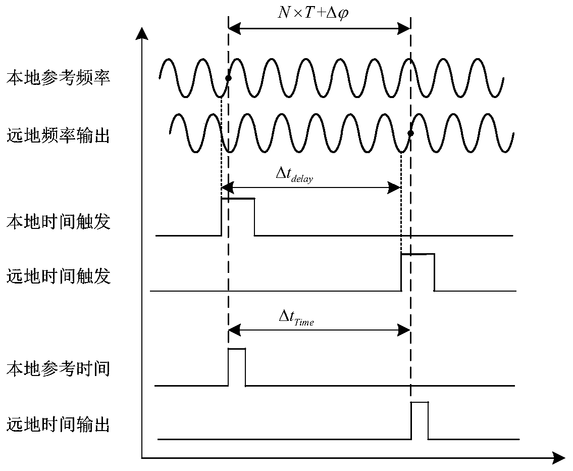
[0048] The embodiment of the present invention provides a high-precision optical fiber time transfer system, the system block diagram is as follows figure 1 As shown, the system includes a local reference frequency signal generation module (may include a frequency conversion module), a local trigger time signal generation module (may include a time conversion module), a local reference time-frequency synchronization module, a local return time-frequency synchronization module, and a loca...


PUM


Abstract

The invention discloses a high-precision optical fiber time transmission system which comprises a local reference frequency signal generation module, a local trigger time signal generation module, a local high-precision time frequency synchronization module, a local time frequency transmission device, a local return time frequency synchronization module, a far-earth time frequency transmission device and a far-earth high-precision time frequency synchronization module. The system is based on a high-precision time signal generation and transmission technology of time frequency signal phase synchronization. Phase locking of the demodulated and recovered time signal and the demodulated and recovered frequency signal is achieved through the high-precision time-frequency synchronization module,a low-jitter time signal synchronous with the phase of the frequency signal in real time is generated, and transmission of the high-precision time signal is achieved while the time signal is output.Meanwhile, the invention provides a high-precision optical fiber time transmission method. According to the invention, the phase locking of the rising edge of the time signal and the sine frequency signal is realized, and the high-stability frequency signal is utilized to generate the low-jitter time signal synchronous with the phase of the high-stability frequency signal, so that the high-precision transmission of the time signal is realized.

Description

technical field [0001] The present invention relates to the technical field of time signal transmission, in particular to a high-precision optical fiber time transmission system and method, which phase-locks the rising edge of the time signal transmitted to the remote end with the frequency signal transmitted to the remote place, Using a high-stability frequency signal to generate a low-jitter time signal that is phase-synchronized to achieve high-precision time transfer, it is mainly used for precise time synchronization and high-precision time comparison. Background technique [0002] Clock synchronization is a basic application requirement. A single frequency transmission cannot meet this requirement, so ultra-high-precision time signal transmission becomes a key technology. The high-precision time-frequency transfer system has very important applications in the fields of deep space exploration, very long baseline interferometry and metrology. The characteristics of hig...

Claims


Application Information

Patent Timeline
Patent Type & Authority Patents(China)
IPC IPC(8): H04J3/06H04B10/25
CPCH04B10/25H04J3/0635
Inventor 程楠应康吴瑞刘雷蔡海文桂有珍
Owner SHANGHAI INST OF OPTICS & FINE MECHANICS CHINESE ACAD OF SCI
Why Eureka
Eureka Blog
Learn More