Dielectric resonator, dielectric wave filter, oscillator, shared apparatus and electronic apparatus thereof

A resonator and filter technology, applied in resonators, circuits, electrical components, etc., can solve the problems of filter characteristic damage, large external size of the device, adjustment screw insertion loss, etc., and achieve good splitting characteristics and low insertion loss. Effect

Inactive Publication Date: 2004-01-07
MURATA MFG CO LTD
View PDF0 Cites 0 Cited by
  • Summary
  • Abstract
  • Description
  • Claims
  • Application Information

AI Technical Summary

Problems solved by technology

[0008] However, when metal adjustment screws are used, when the adjustment screws are close to the resonator element, the insertion loss of the adjustment screws and the unloaded Q decrease
For this reason, when a dielectric resonator i

Method used


Image

  • Dielectric resonator, dielectric wave filter, oscillator, shared apparatus and electronic apparatus thereof
  • Dielectric resonator, dielectric wave filter, oscillator, shared apparatus and electronic apparatus thereof
  • Dielectric resonator, dielectric wave filter, oscillator, shared apparatus and electronic apparatus thereof

Examples


Embodiment Construction

[0043] A first embodiment of the present invention will be described with reference to FIGS. 1 to 6

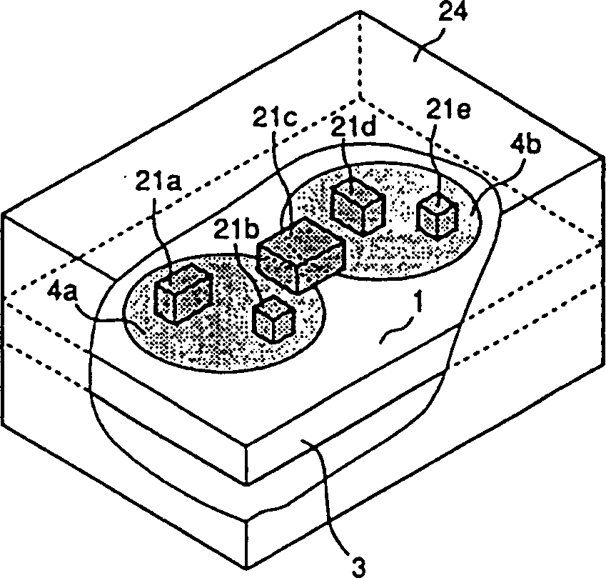
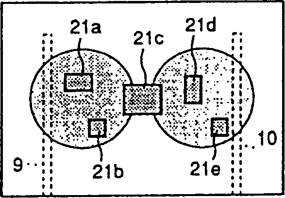
[0044] Figure 1A It is a cut-away perspective view of a part of a dielectric filter. Figure 1B It is a schematic plan view of the dielectric filter after removing the protective box of the dielectric filter. Figure 1A The intermediate dielectric plate 3 is made of dielectric ceramics, and on the upper surface of the dielectric plate are electrodes 1 having electrode non-forming portions 4a and 4b. On the lower surface of the dielectric plate 3, there are electrode non-forming portions 4a, 4b that face each other and have the same shape and size as 4a and 4b, so that the electrode non-forming portions face each other, respectively, in the TEO1O mode. as a dielectric resonator section. The resonant frequency of these dielectric resonators is, for example, in the 20GHZ band.

[0045] The parallelepiped dielectric sheets 21a, 21b, 21c, 21d and 21e are fixed, for example, wi...


PUM


Abstract

The present invention relates to a dielectric resonator device. Electrodes having electrode non-formation sections opposite to each other and having substantially the same shape and size are formed on the opposite main faces of a dielectric plate. The portion of the dielectric plate sandwiched between the electrode non-formation sections opposite to each other is used as a dielectric resonator section. Further, the characteristics of the dielectric resonator device are adjusted by attaching dielectric chips inside of the dielectric resonator section or between adjacent dielectric resonator sections.

Description

technical field [0001] The present invention relates to a dielectric resonator, such as a dielectric filter, an oscillator, a shared device, and a communication device used in a microwave band and a millimeter wave band, each including a dielectric resonator. Background technique [0002] In order to realize advanced mobile communication services and multimedia communication services, it is necessary to transmit large-capacity information at high speed. Therefore, a millimeter wave band having a wide bandwidth is more suitable. In addition to communication, as a new application route that effectively utilizes the characteristics of the millimeter wave band, a motorcycle radar for absorbing collision energy has been made. Millimeter-wave radar can ensure safety, especially in fog or snow, when traditional lidar, which uses light, is ineffective. [0003] If a conventional circuit structure mainly formed of microstrip lines is used for the millimeter wave band, the Q value d...

Claims


Application Information

Patent Timeline
IPC IPC(8): H01P1/20H01P1/201H01P1/208H01P1/213H01P7/10
CPCH01P7/10H01P1/2084H01P1/201H01P1/205
Inventor 三上重幸平塚敏朗园田富哉井田裕金川洁
Owner MURATA MFG CO LTD
Why Eureka
Try Eureka