
Large-scale single-aperture radio telescope and method for improving pointing error of large-scale single-aperture radio telescope

A radio telescope, single-aperture technology, applied in the field of adjustable self-adaptive sub-reflector to improve pointing error, in the field of large-scale single-aperture radio telescope, can solve the problems that cannot be solved, difficult to control, and high cost, and achieves control of heat dissipation speed, small size, light weight effect

Active Publication Date: 2021-09-17
HANGZHOU DIANZI UNIV
View PDF9 Cites 0 Cited by
  • Summary
  • Abstract
  • Description
  • Claims
  • Application Information

AI Technical Summary

Problems solved by technology

[0004] At present, the form of self-adaptive main reflector is used to control the relative displacement of sub-surface panels to compensate the influence of solar thermal deformation on pointing error, but this spliced ​​main surface structure has many problems such as high cost and difficult control, and is not suitable for Modification of Existing Large Antennas
On the other hand, the adaptive main reflector system cannot solve the "solar cooker" problem in the secondary reflector

Method used


Image

  • Large-scale single-aperture radio telescope and method for improving pointing error of large-scale single-aperture radio telescope
  • Large-scale single-aperture radio telescope and method for improving pointing error of large-scale single-aperture radio telescope
  • Large-scale single-aperture radio telescope and method for improving pointing error of large-scale single-aperture radio telescope

Examples


Embodiment Construction

[0031] The present invention will be further described below in conjunction with accompanying drawing.

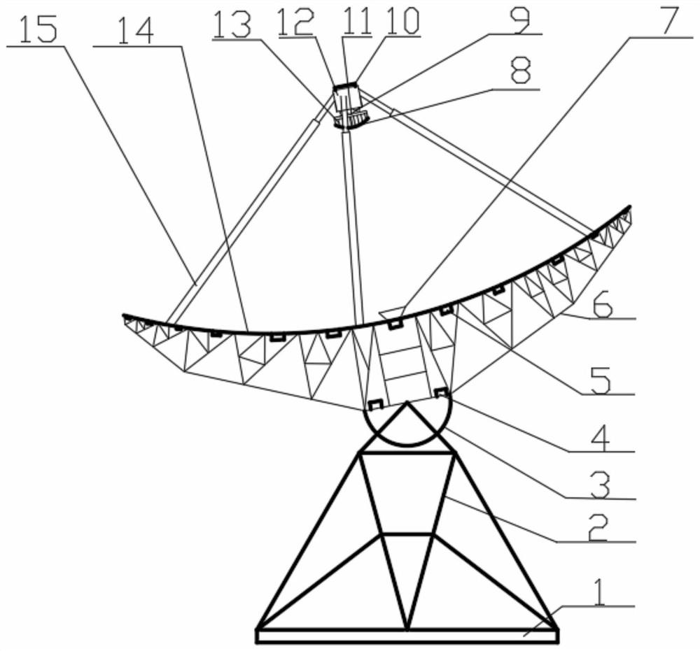
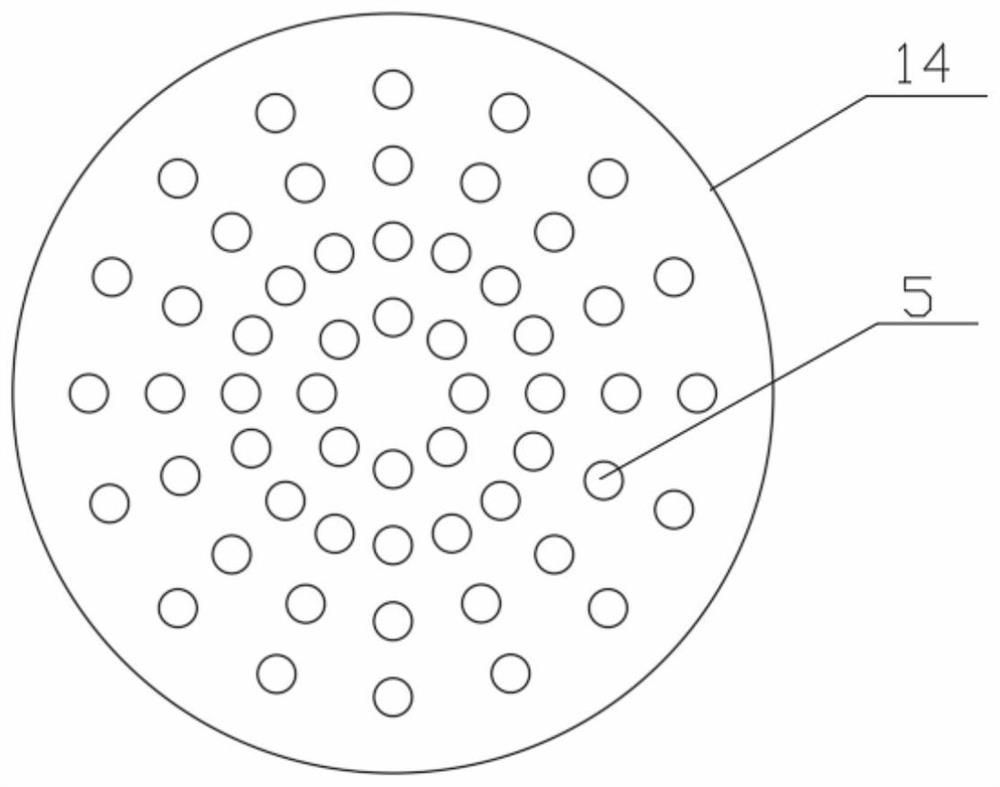
[0032] Such as figure 1 As shown, a large single-aperture radio telescope consists of an azimuth adjustment mechanism 1, an azimuth mount 2, a pitch mechanism 3, a pitch angle sensor 4, an azimuth angle sensor, a temperature strain sensor-5, a truss-type back frame structure 6, a receiver 7, The sub-reflection surface 8, the angle control actuator 9, the platform 11, the connector 12, the displacement control actuator 13, the main reflection surface 14 and the electric cylinder 15 are composed. The azimuth adjustment mechanism 1 is used to drive the azimuth mount 2 to adjust the azimuth angle; the azimuth mount 2 plays a supporting role; the pitch frame of the pitch mechanism 3 is fixed on the azimuth mount 2, and the pitch mechanism 3 is used to adjust the truss-type back frame structure 6 The pitch angle; the main reflector 14 is connected with the truss type back frame ...


PUM


Abstract

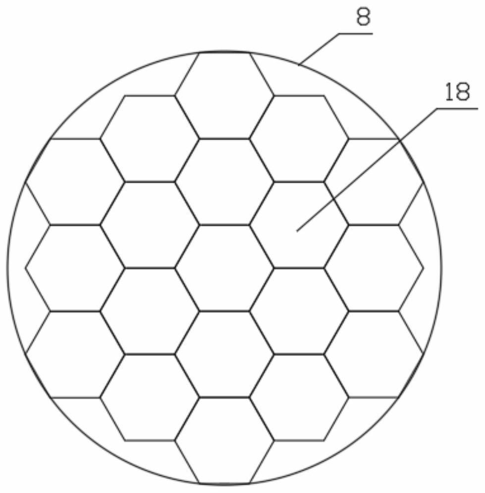
The invention discloses a large-scale single-aperture radio telescope and a method for improving a pointing error of the large-scale single-aperture radio telescope. A main reflecting surface is connected with a truss type back frame structure through a plurality of temperature strain sensors I; an azimuth angle sensor monitors the azimuth angle of the azimuth seat frame; a pitch angle sensor monitors the pitch angle of the truss type back frame structure; a connecting part is connected with the main reflecting surface through more than three electric cylinders; a platform is connected with the connecting part through a plurality of angle control actuators; an auxiliary reflecting surface is composed of a plurality of block units and shape correction blocks. The shape correction blocks are fixed with the platform; the block units are connected with the platform through a plurality of displacement control actuators; a heat dissipation device and a plurality of second temperature strain sensors are fixed to the back surfaces of the block units. On the basis of the ray tracing technology and the deep learning optimization algorithm, the offset prediction model of the main reflecting surface and the temperature prediction model of the main reflecting surface and the auxiliary reflecting surface are established. The self-adaptive adjustment of the surface shape precision and the pointing precision of the auxiliary reflecting surface and self-adaptive heat dissipation of the heat dissipation device on the auxiliary reflecting surface are achieved.

Description

technical field [0001] The invention belongs to the technical field of radio telescopes, and specifically relates to a large-scale single-aperture radio telescope and a method for improving the pointing error of the large-scale single-aperture radio telescope by using an adjustable self-adaptive sub-reflector. Background technique [0002] A radio telescope is a high-gain radio signal collection and detection device, especially suitable for dark matter, pulsars, gravitational waves, black holes and other deep space exploration fields. The aperture area and surface accuracy of the main reflector directly affect the reception of signals. capacity and its reception efficiency. As a result, radio telescopes are showing a development trend of larger and larger apertures, higher and higher surface accuracy, and more and more complex structures. At the same time, pointing accuracy has become an important performance index for large radio telescopes. [0003] The reflector part of ...

Claims


Application Information

Patent Timeline
Patent Type & Authority Applications(China)
IPC IPC(8): H01Q15/14H01Q19/10H01Q1/00H01Q23/00G06F30/23G06F30/27G06N3/08G06F119/08
CPCH01Q15/147H01Q19/10H01Q1/02H01Q23/00G06F30/23G06F30/27G06N3/08G06F2119/08
Inventor 李蓉吴占彬翁佳豪陆伟张巨勇陈志平
Owner HANGZHOU DIANZI UNIV
Learn More