Wire clamping device of hot-line work robot and operation method thereof

A technology for live work and wire clamps, applied in the directions of circuit/collector parts, circuits, electrical components, etc., can solve the problems of overload damage to the robot arm, the operation cannot be carried out normally, and the risk of failure to catch the wire is high, so as to overcome the load Insufficient, improve the success rate of grabbing, improve the effect of working efficiency

Active Publication Date: 2021-09-17
YIJIAHE TECH CO LTD
View PDF3 Cites 1 Cited by
  • Summary
  • Abstract
  • Description
  • Claims
  • Application Information

AI Technical Summary

Problems solved by technology

[0002] 10KV live work often requires operations such as clamping, threading, hanging, and threading of branch lines. At present, insulating clamping rods are generally used in the industry to implement. The insulating clamping rod is composed of two insulating rods and the clamping pliers. The structure is bulky. When clamping the wire, it needs to apply force to maintain the clamping state, which is time-consuming and labor-intensive, and there is a risk of loosening.
[0003] At present, although the wire clamps carried by some live working robots on the market can realize some cable clamping operations, they also have certain limitations: due to mechanical The load at the end of the arm is limited, so the thread clamp can only move closer to the light weight direction, so the problem is that the opening of the thread clamp is small, and the risk of failure to grasp the thread is greater. After grasping, the mechanical arm moves along the branch line , the branch line will bring a lot of resistance, which will cause the robot arm to be overloaded and damaged, and the work cannot be carried out normally. This has also become one of the difficulties that the robot needs to solve in live work.

Method used


Image

  • Wire clamping device of hot-line work robot and operation method thereof
  • Wire clamping device of hot-line work robot and operation method thereof
  • Wire clamping device of hot-line work robot and operation method thereof

Examples


Embodiment Construction

[0025] Preferred embodiments of the present invention will be described below in conjunction with the accompanying drawings, and the technical solution of the present invention will be explained more clearly and completely.

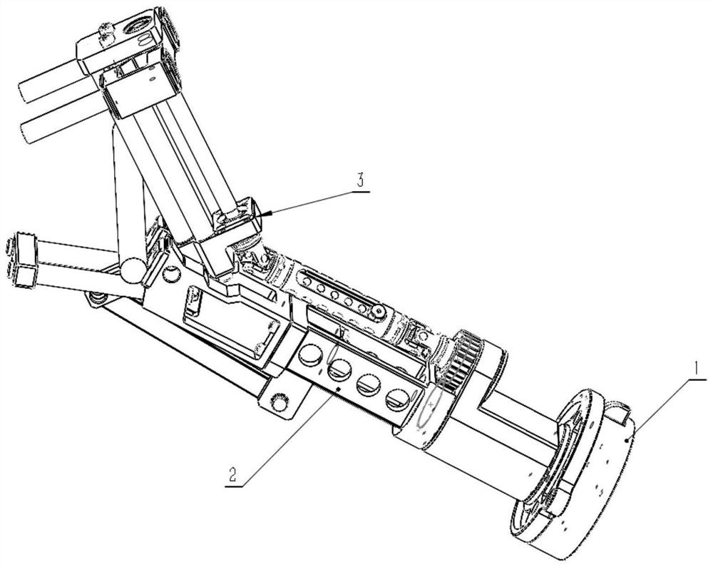
[0026] Such as figure 1 Shown is a new type of tensioner for a live working robot, which includes a docking assembly 1 , a fixed jaw assembly 2 , and a movable jaw assembly 3 .

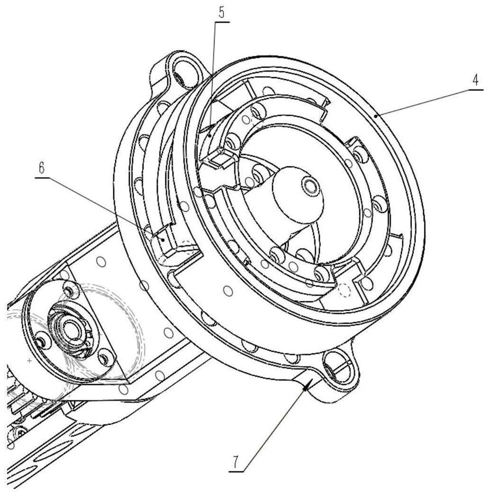
[0027] Such as figure 2 As shown, the docking assembly 1 includes a tool tray 4, an inclined plane block 5, a locking lever 6, and a guide positioning plate 7, wherein three inclined plane blocks 5 are connected to the tool tray 4 by screws, and the locking lever 6 is connected to the tool tray 4 A spring is compressed between them, connected by a straight pin, and the guiding positioning disc 7 and the tool disc 4 are fixed by screws.

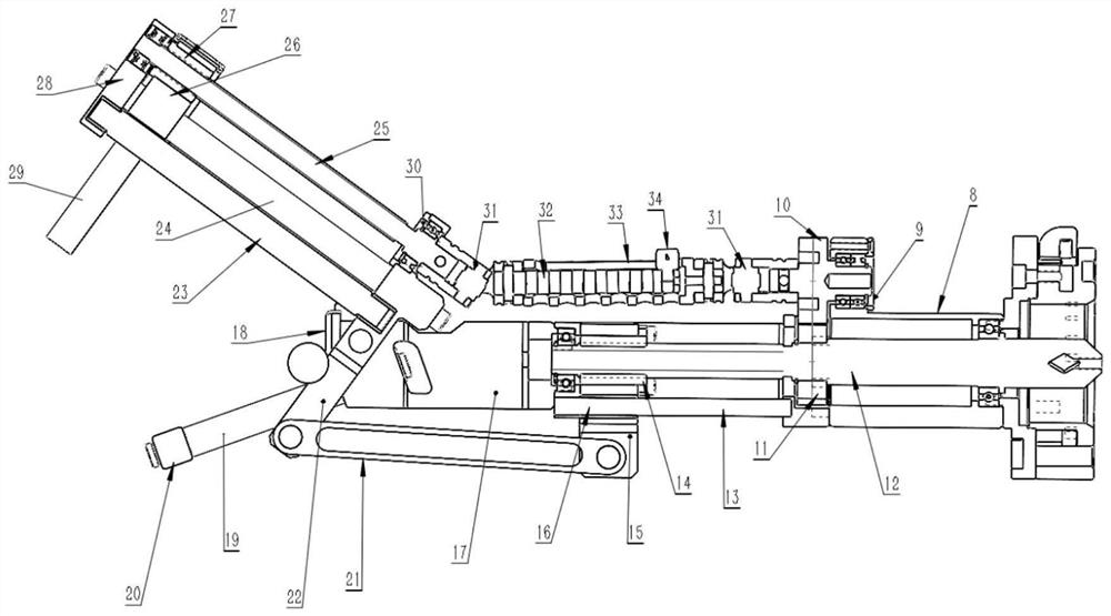
[0028] Such as image 3 As shown, the fixed jaw assembly 2 includes a gear base 8, a thread clamping screw rod 12, a thread clamping base 13...


PUM


Abstract

The invention discloses a wire clamping device of a hot-line work robot and an operation method thereof.The wire clamping device comprises a fixed claw assembly and a movable claw assembly; the fixed claw assembly comprises a wire clamping support and a lower rolling shaft; the movable claw assembly comprises an upper rolling shaft, a wire clamping swing rod and a connecting rod; the lower rolling shaft is connected to the wire clamping support; the upper rolling shaft is connected to one end of the wire clamping swing rod; the middle of the wire clamping swing rod is hinged to the wire clamping support; the other end of the wire clamping swing rod is hinged to the connecting rod; and the connecting rod drives the wire clamping swing rod to rotate to achieve opening and closing control between the upper rolling shaft and the lower rolling shaft, and then wire clamping operation is achieved. The wire clamping device tool has high adaptability and compatibility to a robot, and a large opening can be achieved while the light design requirement of the robot is met, so that the grabbing success rate is greatly increased; and resistance brought by branch wires when the robot moves is greatly reduced through the rolling wire stroking design, the operation efficiency is effectively improved, and the risk of manual operation is avoided.

Description

technical field [0001] The invention relates to a thread gripper suitable for live working robots and an operating method thereof, belonging to the technical field of live working robots. Background technique [0002] 10KV live work often requires operations such as clamping, pulling, hanging, and threading of branch lines. At present, insulating clamping rods are generally used in the industry. The insulating clamping rods are composed of two insulating rods and clamps. The structure is bulky, and it needs to apply force to maintain the clamped state when clamping the thread, which is time-consuming and labor-intensive, and there is a risk of loosening. [0003] Although the wire clamps carried by some live working robots on the market can achieve some cable clamping operations, they also have certain limitations: due to the limited load at the end of the mechanical arm, the wire clamps can only be lighter. The direction is closer, so the problem will be that the opening o...

Claims


Application Information

Patent Timeline
Patent Type & Authority Applications(China)
IPC IPC(8): H01R43/00H01R43/027H02G1/04
CPCH01R43/00H01R43/027H02G1/04
Inventor 程敏黄志康胡立鸥刘久晨李鹏
Owner YIJIAHE TECH CO LTD
Why Eureka
Try Eureka